


My job and other things I guess
31/3/2026
For the past year I have been working at a cancer treatment/research hospital as a Linux sysadmin. Our primary service is a high performance cluster (HPC) providing compute resources for both clinical and research purposes. It has been an interesting insight into cluster computing and administrating Linux systems in a production environment with many users. My previous IT work has been in a Windows environment.
I haven't been the happiest person for a while.
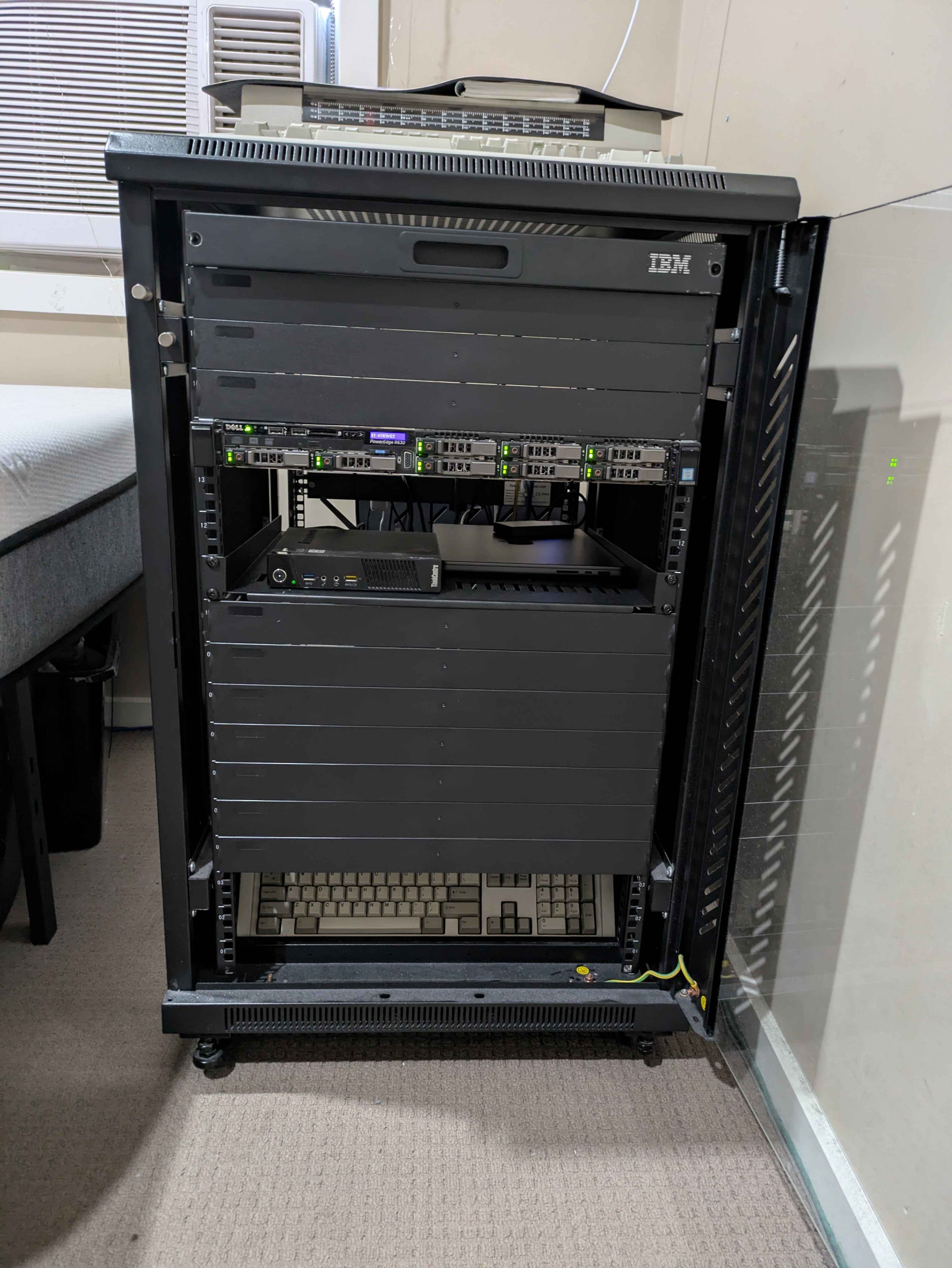
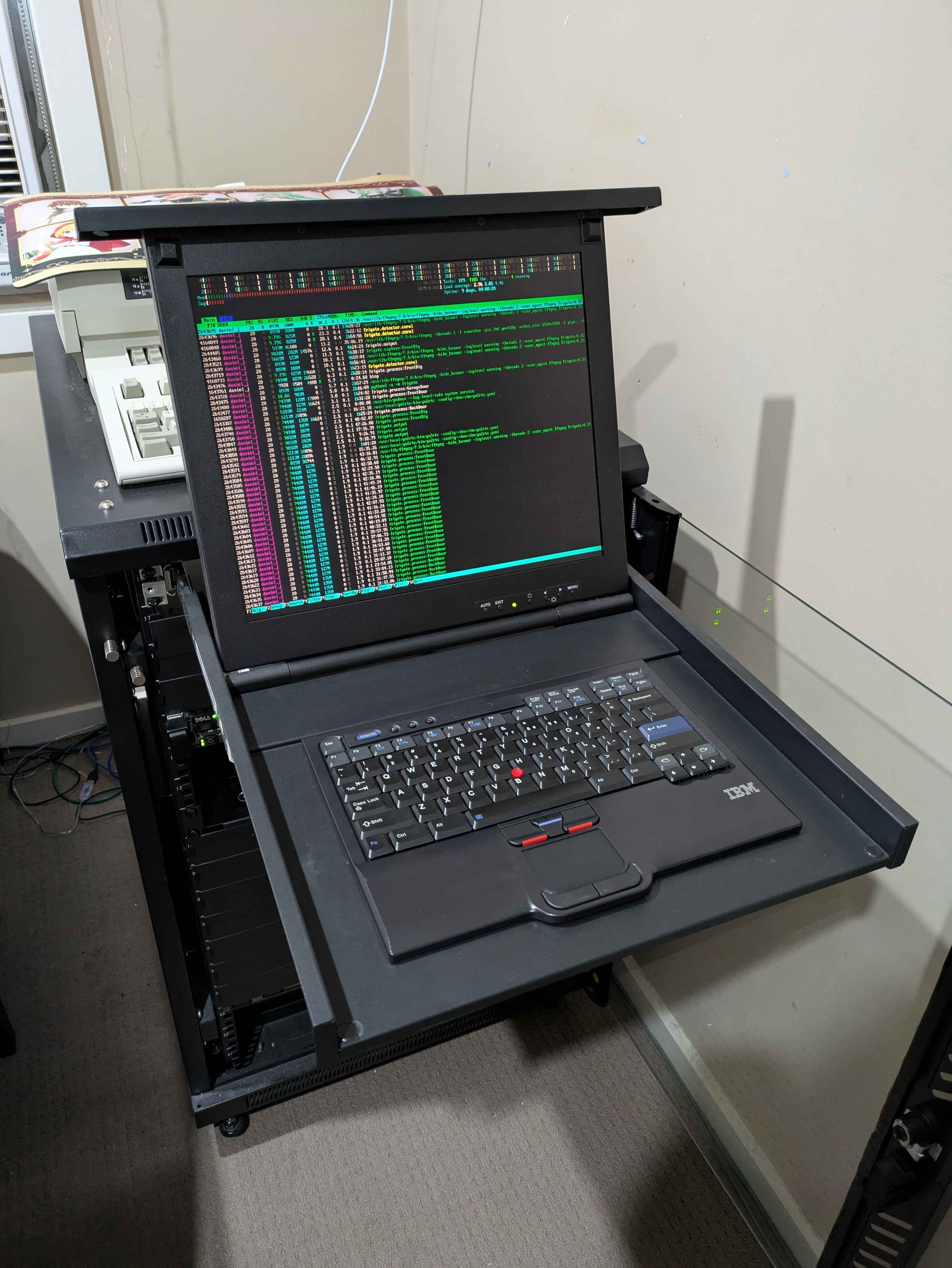
For a while now I have had a 20U server rack in my room. It has a Dell PowerEdge R630, IBM console, a Lenovo ThinkCentre M93p and a 1320W UPS. There is also an M4 Macbook Pro stored in there as a VPN client for work.
The ThinkCentre is my HomeAssistant instance with a Google Coral for inference, Bluetooth dongle and SONOFF ZBDongle-E for Zigbee and Thread.
The R630 has:
- 2x Intel(R) Xeon(R) CPU E5-2687W v4 @ 3.00GHz
- 208GB DDR4 ECC Memory
- 2x 500GB SATA SSD's in RAID 1 for the OS
- 8x 1.5TB SAS drives in raidz1-0 for 11TB usable storage
- Frigate with 5 cameras, 24/7 recording
- Jellyfin with live TV and a media collection
- CS2 server
- Various little services and tools
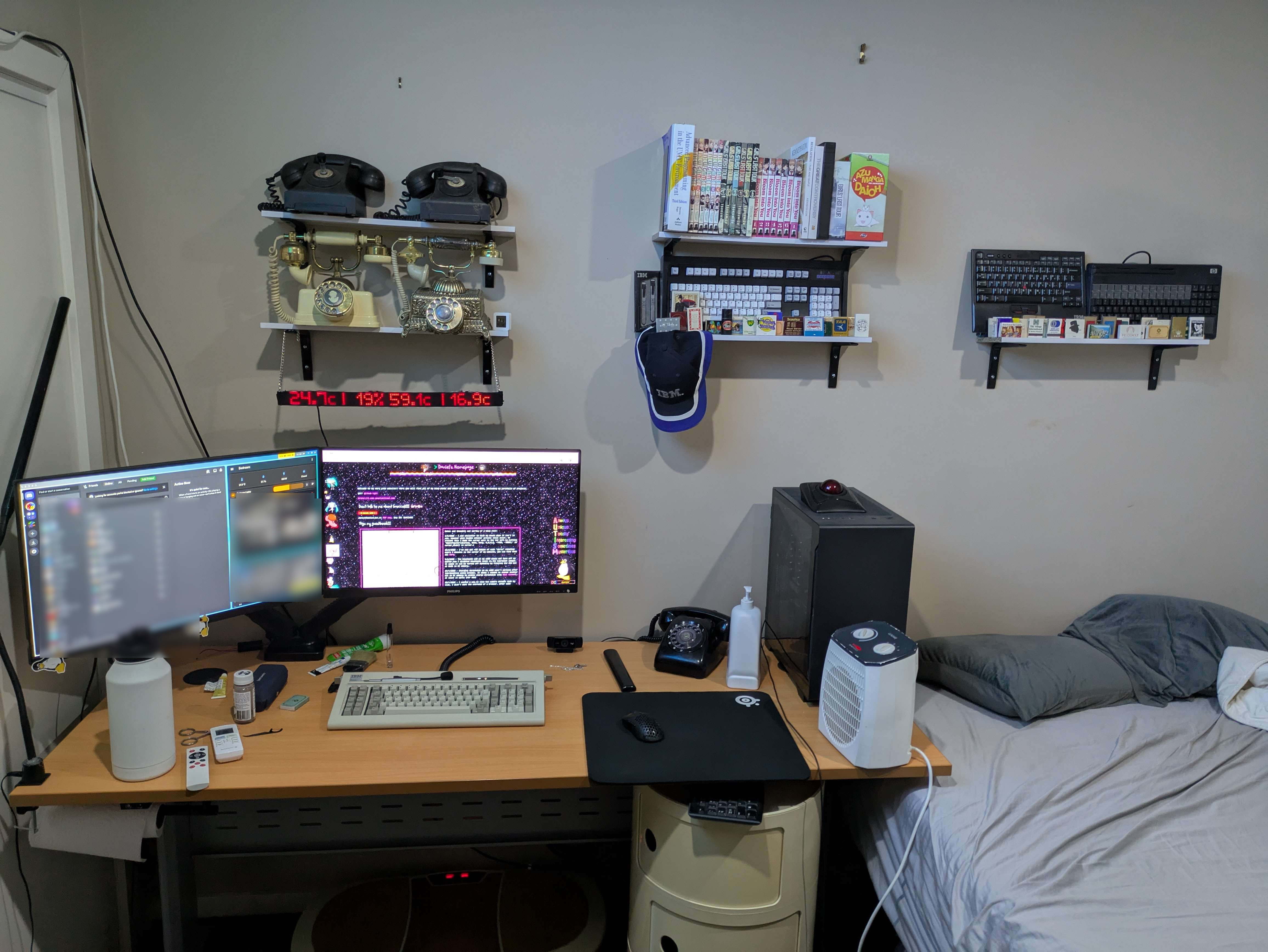
I now have 3 32 inch monitors on a triple arm mount which is nice.
The UPS in my rack is connected to my server which runs NUT. The home assistant machine is a remote client to NUT and is powered off safely along with the R630 as appropriate.
The IBM KVM was a very cool addition. I had originally bought it on eBay, but it arrived damaged. I got my money back from that and it turns out someone I know irl had one kicking around, and that works. So I scored one free plus a spare USB IBM keyboard - which sell for ~130 online.
My mental health has been very low for a while, so I've had no motivation to do projects, just doing my job is hard enough. I'm grateful to get to work from home. Honestly, if I had to travel to the city every day for work I'd have quit by now. I will never attend a job full-time on-site again, it just isn't reasonable anymore.
Oh yeah, I guess that's something I never said on here, I now live in the Melbourne area. Really shitty situation forced me to come here. I miss my old hometown and one (1) person there but if I stayed there I'd have definitely killed myself by now - here it's only slightly less likely.
Anway, here's the server, isn't it cool? Power draw sucks, it sits at around 168W constantly.
ok bye see you next year ( ╥﹏╥) ノシ


Setting my rooms lighting to match my background
5/3/2025
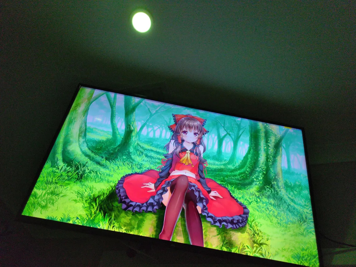
I use Home Assistant for various things, one is controlling the two RGB lightbulbs in my room.
I have recently put a TV up on my wall, when I am not watching something on it, I generally leave it with the background showing. I've found at night when I turn my lights down it creates a nice warm glow of color. So I decided to automatically change my lights color to match that of the background.
The script is pretty simple, it sets the background (swww daemon) to a random image every 5 minutes. I take the average color of that image and send it to Home Assistant which sets my rooms lights to match this color. The brightness is controlled by me.
I also added a toggle inside Home Assistant that can disable the scripts ability to change the lights, this is so during the day when I just want normal lighting I can turn it off easily.

This is the script:
#!/bin/bash

sleep 2

if [[ $# -lt 1 ]] || [[ ! -d $1   ]]; then
    echo "Usage:
    $0 "
    exit 1
fi

# Edit below to control the images transition
export SWWW_TRANSITION_FPS=60
export SWWW_TRANSITION_STEP=2

INTERVAL=300

HA_URL="http://URL:8123"
BEARER_TOKEN="TOKEN"
hex_to_rgb() {
    hex=$1
    r=$(echo $((16#${hex:1:2})))
    g=$(echo $((16#${hex:3:2})))
    b=$(echo $((16#${hex:5:2})))
    echo "$r,$g,$b"
}


while true; do
    find "$1" -type f \
    | while read -r img; do
        echo "$((RANDOM % 1000)):$img"
    done \
    | sort -n | cut -d':' -f2- \
    | while read -r img; do
        swww img "$img"
        color=$(convert ${img} -resize 1x1 txt:- | grep -Po "#[[:xdigit:]]{6}")
        rgb=$(hex_to_rgb $color)
        # Check if light control is enabled by checking the input_boolean state
        light_control_enabled=$(curl -s -X GET -H "Authorization: Bearer $BEARER_TOKEN" \
        "$HA_URL/api/states/input_boolean.light_control_enabled" | jq -r '.state')

        if [ "$light_control_enabled" != "on" ]; then
            echo "Light control is disabled."
        else
            curl -X POST -H "Authorization: Bearer $BEARER_TOKEN" \
            -H "Content-Type: application/json" \
            -d "{\"entity_id\": \"light.bedroom_lights\", \"rgb_color\": [$rgb]}" \
            $HA_URL/api/services/light/turn_on
        fi
        curl -X POST http://192.168.1.216/pump -H "Content-Type: application/json" -d "{\"avgcol\": \"${color}\"}"
        sleep $INTERVAL
    done
done

My room and the cool things in it ♥
2/3/2025
It has been a while since I posted my room and the cool stuff in it. So here it is without any cleaning up, because that would be too fake.


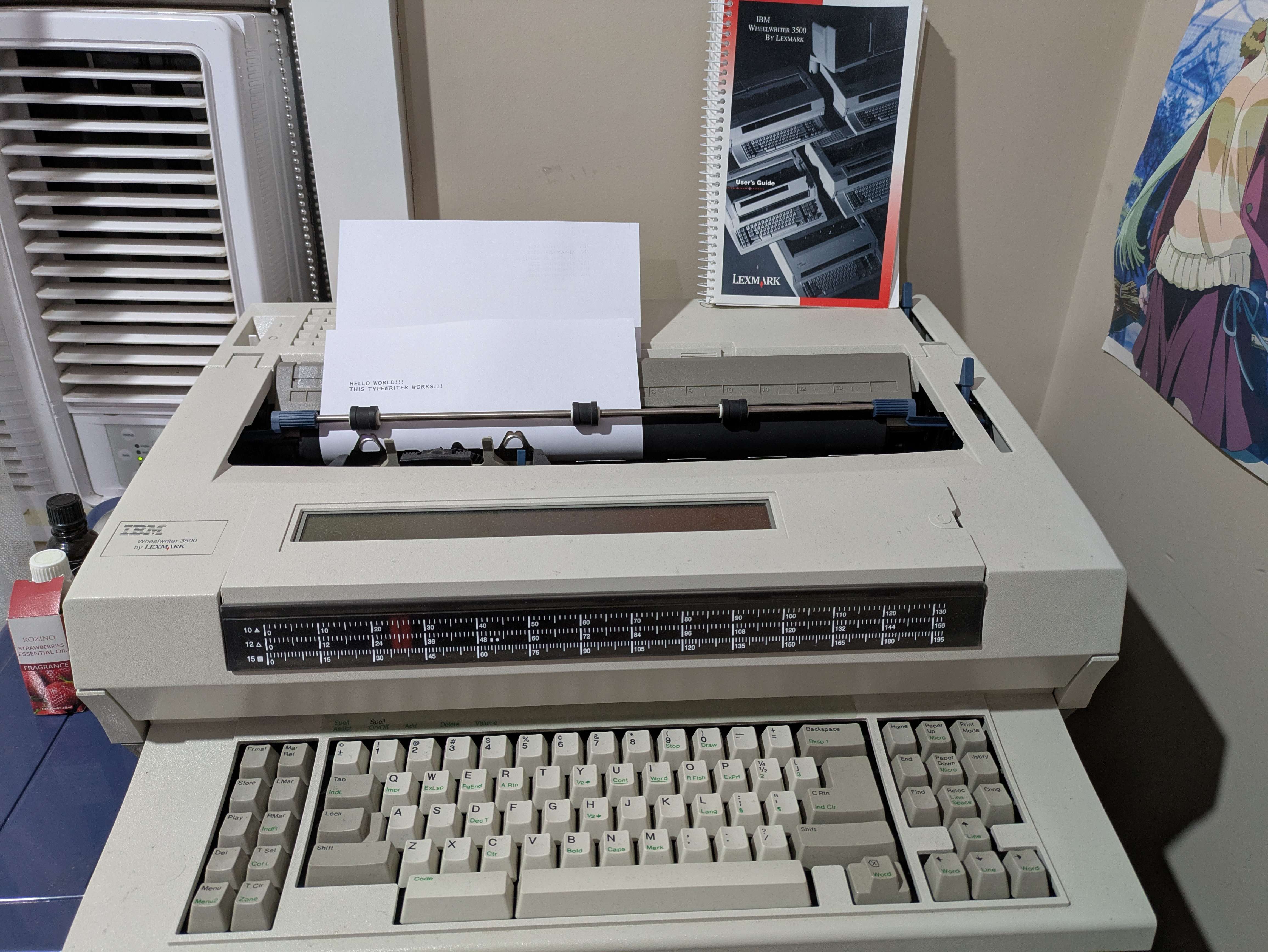
- IBM WheelWriter 3500 typewriter in working condition
- Multiple rotary and hand crank phones
- Including 2 linesman test phones
- I have a phone network in my house, the rotary phone on my desk works and can call other phones in the house
- IBM Model M and F collection
- Manga
- Fumos and Figures
- IBM hat and pen set
- Matchbook/matchbox collection
- LED Matrix sign project showing inside/outside temperature, as well as CPU usage and temperature
- This is a project of mine made using an ESP32 and has a web control panel/REST API

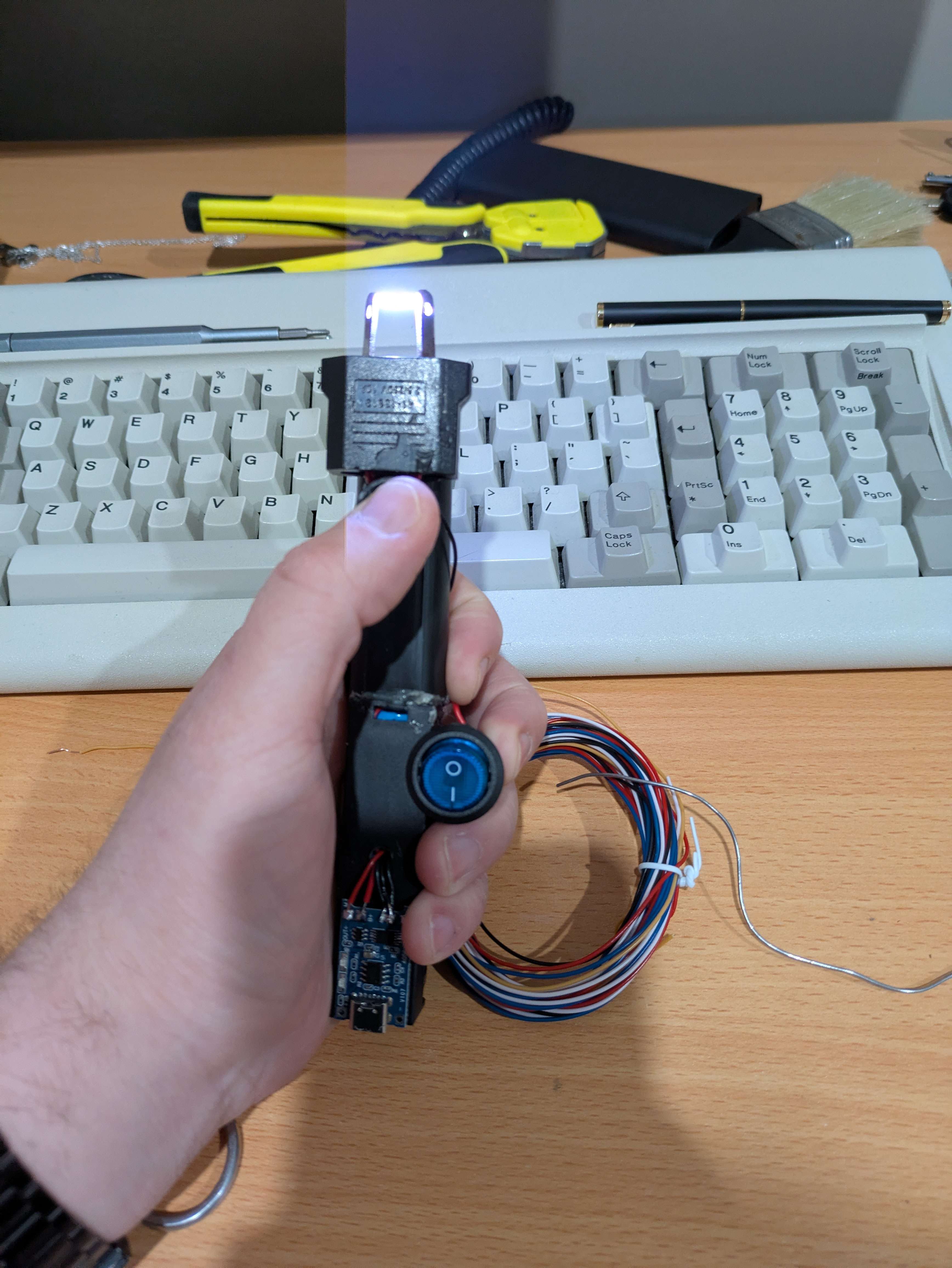
I call him Mr. Zappy
25/1/2025
He's powered by an 18650, USB-C rechargable.


Exploring and having fun with rotary telephones
24/11/2024
Origin of the idea
Someone I live with has become a little frustrated with trying to get my attention. They're not comfortable knocking on my door as they don't want to disturb me and I often cannot hear the knocking due to music. Logically, the solution is to just call my mobile phone, but they said they don't want to do that. An intercom system was (jokingly) brought up by them, so I told them I'll install rotary phones in the living area and my room and they can just call me.This obviously breaks their requirement of not just calling me, but it sounded like a lot of fun, so i'm doing it anyway.
How to do this?
I know very little about phone systems and unfortunately did not experience the age of analog telephony. My research for this project may have produced misinformation, so what I am writing here may not be correct. It is just the culmination of my weekend researching.Turning to the internet to start researching the idea, I found creating a basic intercom between two analog phones is actually really easy. All you need is a ~9v power supply and a ~200 ohm resistor. This is cool and all, but the big flaw is you cannot ring the other phone. Both phones need to be off the hook for this to operate. I want to experience the delight of the bells and dialing.
I had the vague knowledge of this requiring a PBX. So I started looking for SOHO PBX systems. Through this research I learned analog phones have two kinds of dialing. The first is tone dialing. This is what any modern analog phone uses. Each digit on the keypad generates a tone combining multiple frequencies. This is sent instantly to the endpoint controlling the line which interprets these frequencies.
The other option is pulse dialing. Pulse dialing is a whole lot simpler - each digit on the rotary or keypad sends a pulse down the line, 1 sends 1 pulse, 2 sends 2 pulses ... This is really slow.
Rotary phones use pulse dialing. Knowing this I started looking for a PBX that supported this. I found many cheap PBX systems, however the support for pulse dialing and the ringer voltage/Hz were not compatible (more on that soon). Some more expensive system like the Panasonic KX-TA824 came up, but my budget for this project was too low for this.
I found some really interesting custom designed and built analog PBX systems, however this wasn't within the scope of this project.
The biggest issue I was facing was supporting the ringer. The ringer on most rotary phones requires an AC supply of 75-90V at 17-30Hz. Most cheap SOHO PBX systems supplied the right range of voltage to the ringer, however they serve it at the Hz of its power supply input. Here in Australia, that is 50Hz. This just will not make a ringer operate properly.
While researching I came across a type of device known as an ATA (analog telephone adapter). This is a device used to convert an analog phone into one that supports other systems, like VoIP. Through some searching I came across the GrandStream HT8xx series of devices. Specifically the HT802. This device supports two concurrent analog telephones with local calling, meaning I can call each phone as an extension. My early research proved promising in regards to this device supporting 25Hz 90v ringing. I purchased this device.
Next, of course I needed some rotary phones. I did not have any. I could have purchased some on eBay or the like, however I opted to try find some locally. At this point I found one device:

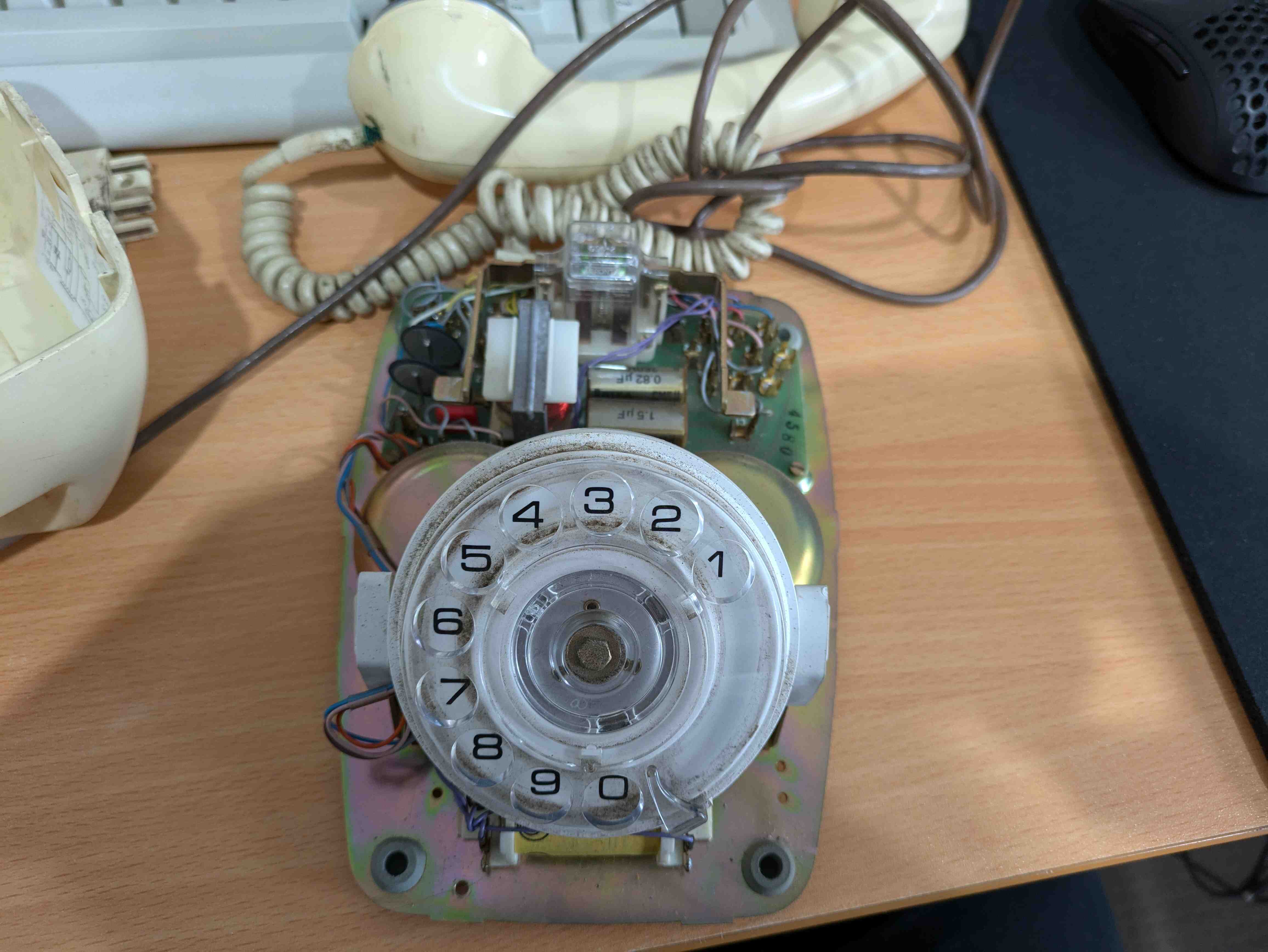
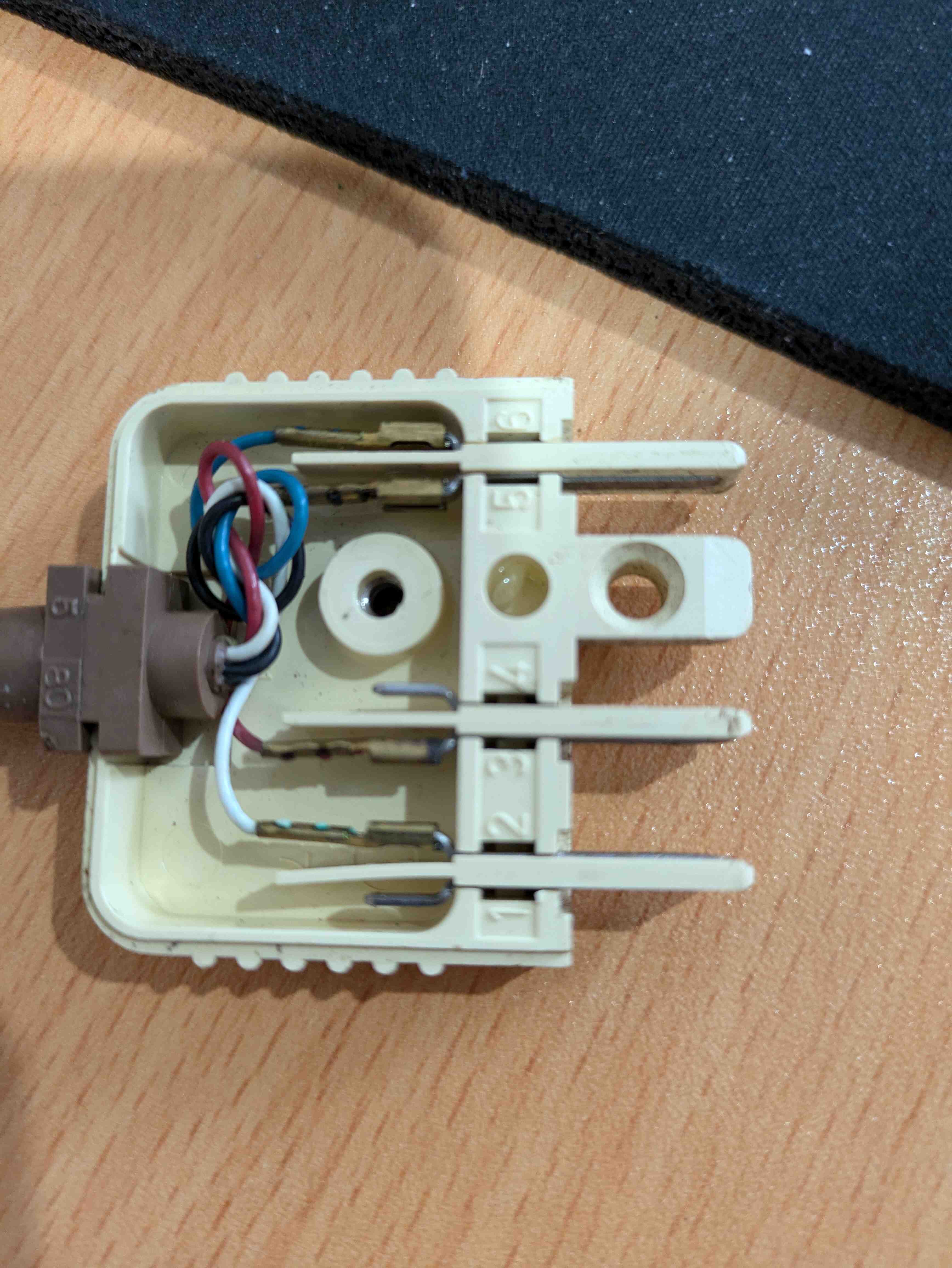
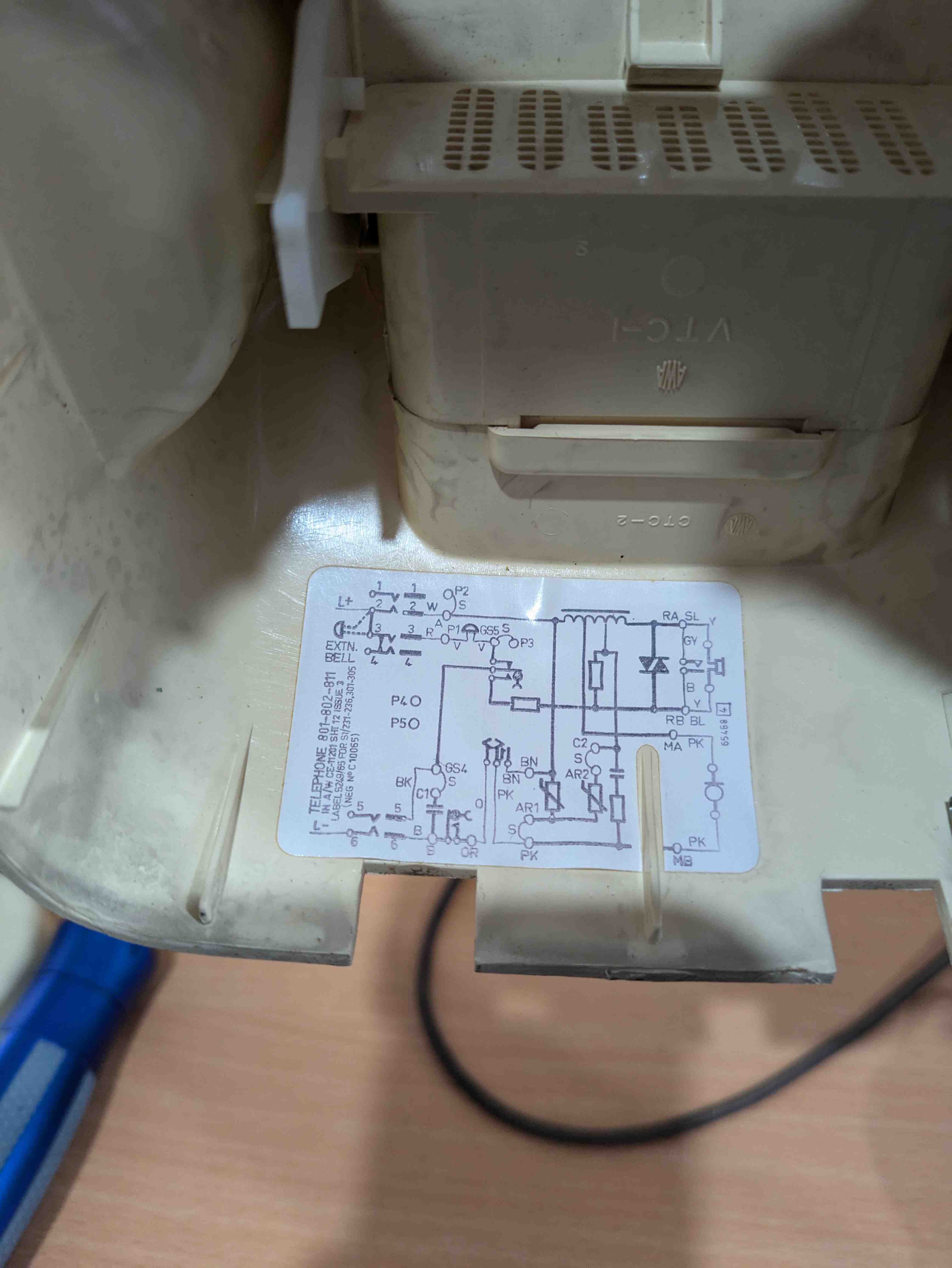
It is REALLY cool to see a device that provides a schematic.
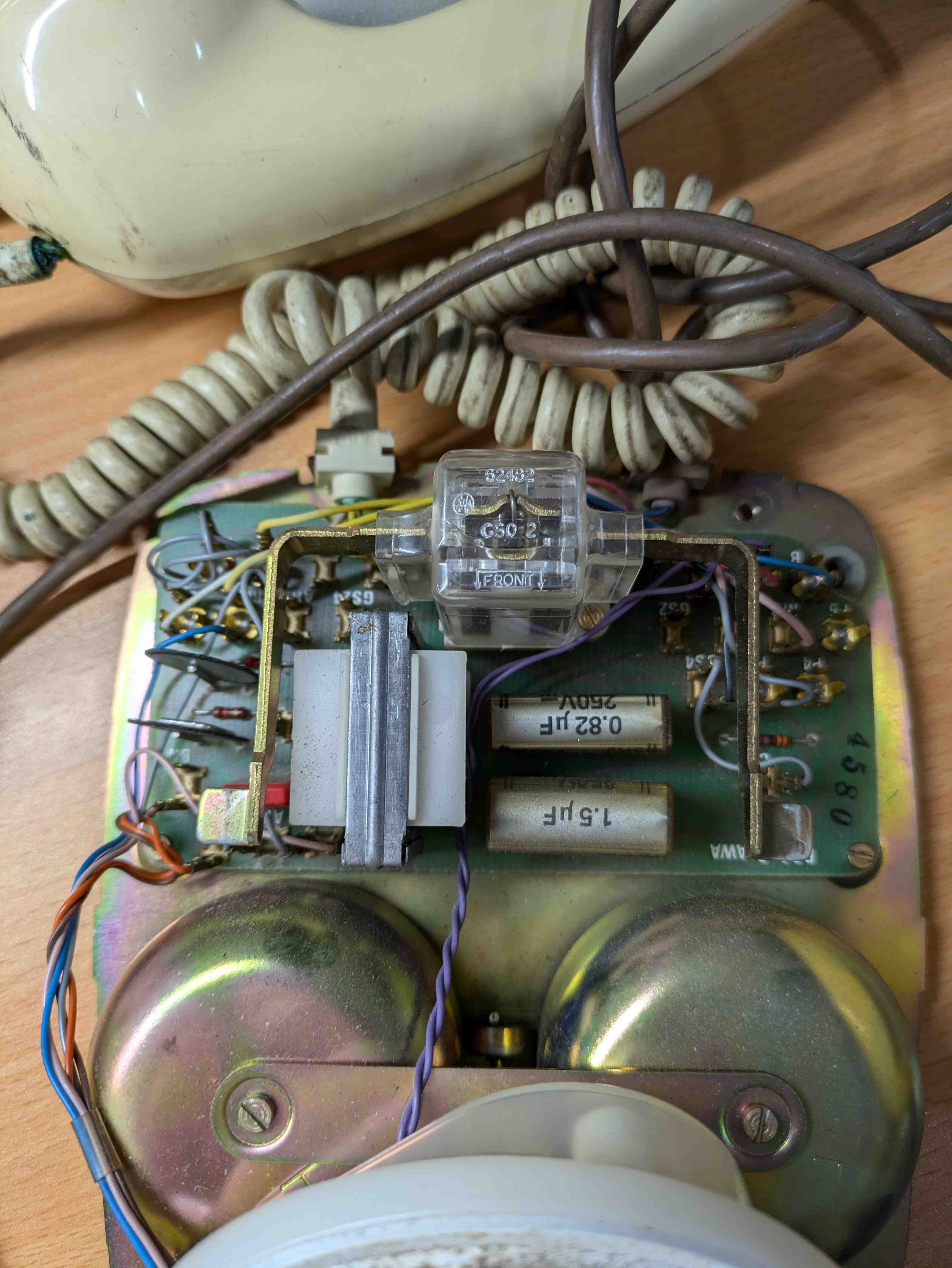
After some cleaning it came up nicely:
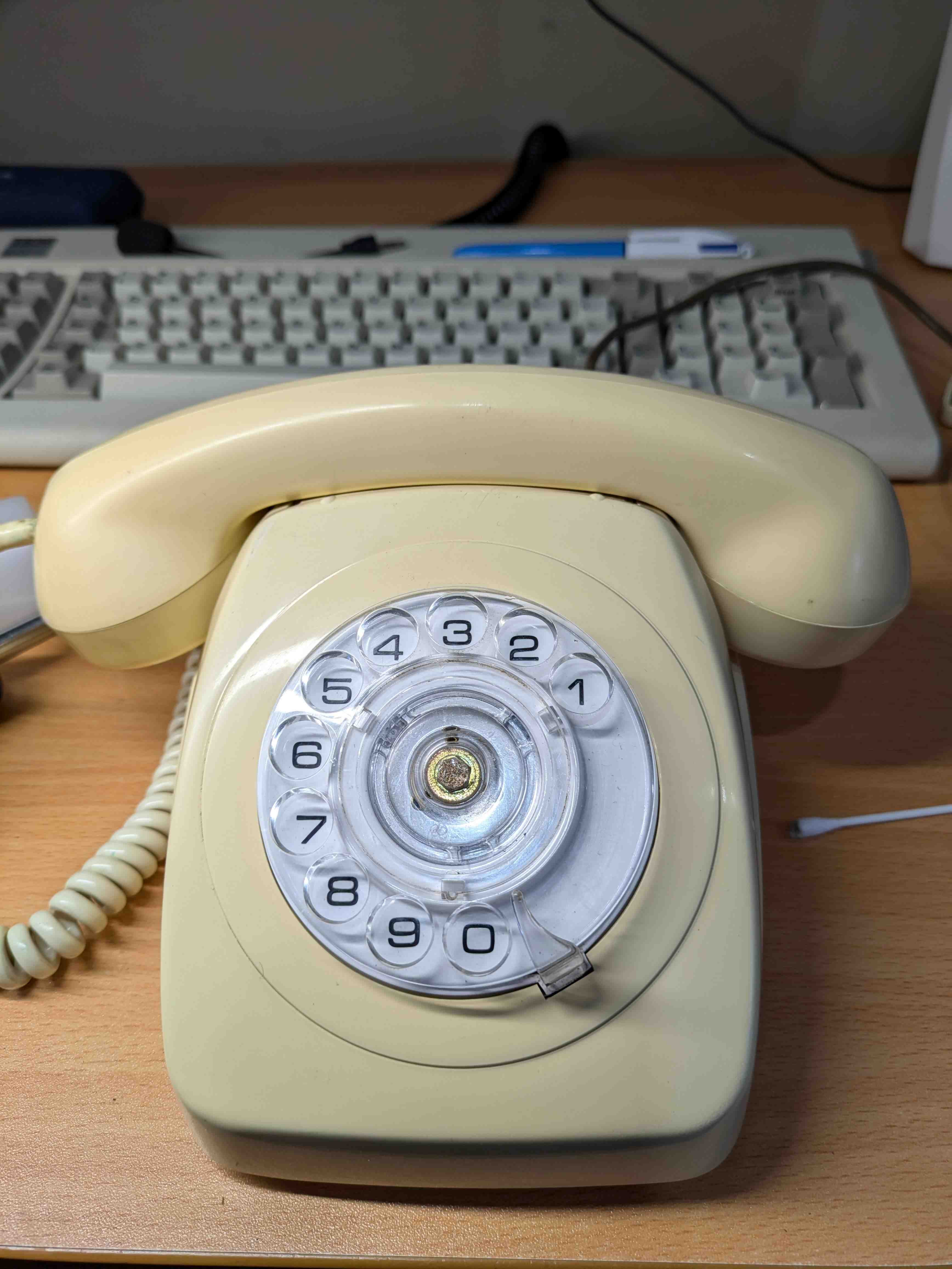
The only other phones available locally were absurdly priced, so I kept looking out for deals on marketplaces.
I purchased a pack of 50 RJ11 crimp connectors and had my first go at crimping. It didn't go too well, really. The internet told me phone cables are 24 gauge, so I blindly purchased a 30M roll of 24 gauge figure 8 wire. I'm not really sure where I went wrong doing this, however the wires with the insulation still on would not fit into the crimp connectors. My solution to this was to strip and tin the wires, at which point they did fit. However they are breaking easily, so this is a pretty bad solution. Then it came time to try and plug the cable into the HT802. It did not fit! The connector had plastic in the way stopping it from going into the port.. Why? Well, it turns out RJ11 is the old standard (I did check the spec sheet for the HT802, and it says RJ11 ports), and instead the HT802 expects RJ12, which is the updated version of RJ12. That was annoying.
With the first phone ready to start testing with, I began with configuring the HT802. Being brand new to analog telephony all of the terms and phone components are alien to me. I wanted a way to test calling the phone and making the ringer sound. For this, I found sip2sip.info, which is a free (with limitations) to use SIP server. Configuring the phones port to use this SIP server (after making an account) seemed to go smoothly, the phone registered itself successfully. So I called the phone from another SIP client. The phone did not ring, and no audio received or transmitted.
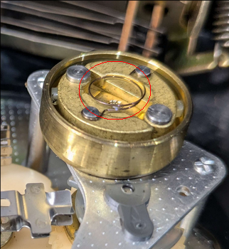
I knew from the beginning I had to configure the port to use high powered ringing. This name led me to assume it'd supply the 90+V required. Checking with a multimeter, it was only ringing at 50V. I thought this would be the problem. After some playing around with settings, I found only 50V is used if the ringing Hz is set to 20Hz. I had not yet switched the port to 25Hz which is required in Australia. Now, the phone is supplied about 100V when ringing. But I still had no ringing. Further research turned up that most phones of this age are configured to expect the wall plug itself to connect two wires together. I am not doing, and found that I instead needed to connect jumper A to P1 inside the phone itself. The phone now sings its beautiful song.
But I am still not getting any audio. This was frustrating me. I tried several NAT traversal methods, none of which worked. Then I realised I had just recently moved, and most ISPs in Australia put your connection on CGNAT. Whoops... I called my ISP and got taken off, audio now worked. sip2sip provides a test number, 3333. I found it plays the theme music to 007: The World is Not Enough. That was a nostalgia hit. I loved that game on N64. But I was stuck on one of the first missions. In the train station I could not find the bomb to defuse, I struggled for weeks. I finally convinced my father to look it up on the internet at work. Turns out it was in the female toilets.
Now I was in a kind of limbo, I needed another phone. Not having found one yet, I wondered if I could get root on the HT802...
Trying to get root on the HT802
I quickly found someone had found a built-in backdoor on the HT8xx devices, as well as created multiple useful firmware decrypting scripts. Unfortunately this backdoor was patched by the oem and I was running the latest firmware. I really don't want to go back to previous firmware. So I thought I'd take my shot at finding a way in.Using the tools provided by BigNerd95, I extracted the firmware my device was running and went hunting for some scripts or binaries to exploit. Most of the logic of the web interface uses haserl. I had never heard of this before, it is an interpreter for shell or Lua scripts to create cgi scripts. I don't consider myself a good programmer and I struggled to find many avenues in these scripts. Looking specifically for any injection opportunities in the interface and nvram variables I can control in their limited shell. They provide a really basic shell via dropbear. Unfortunately, there is no way to launch a proper shell from this menu.
I thought I'd take my shot trying to find an exploit in this shell. I decompiled the executable and tried my hand at finding something. I was not successful here either. I'd love to revisit this at some point with better knowledge to find a way to do this programmatically.
So my next thought was serial port. Of course, on the board of the device there are exposed pads for a serial port. I hooked up the board to my esp32 running a serial to TTL proxy, and hoped for the best.
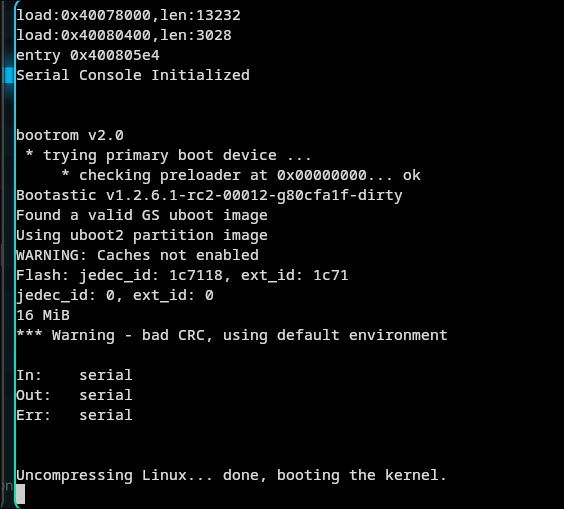
It works, but sadly they have disabled console access on the port once the kernel loads.
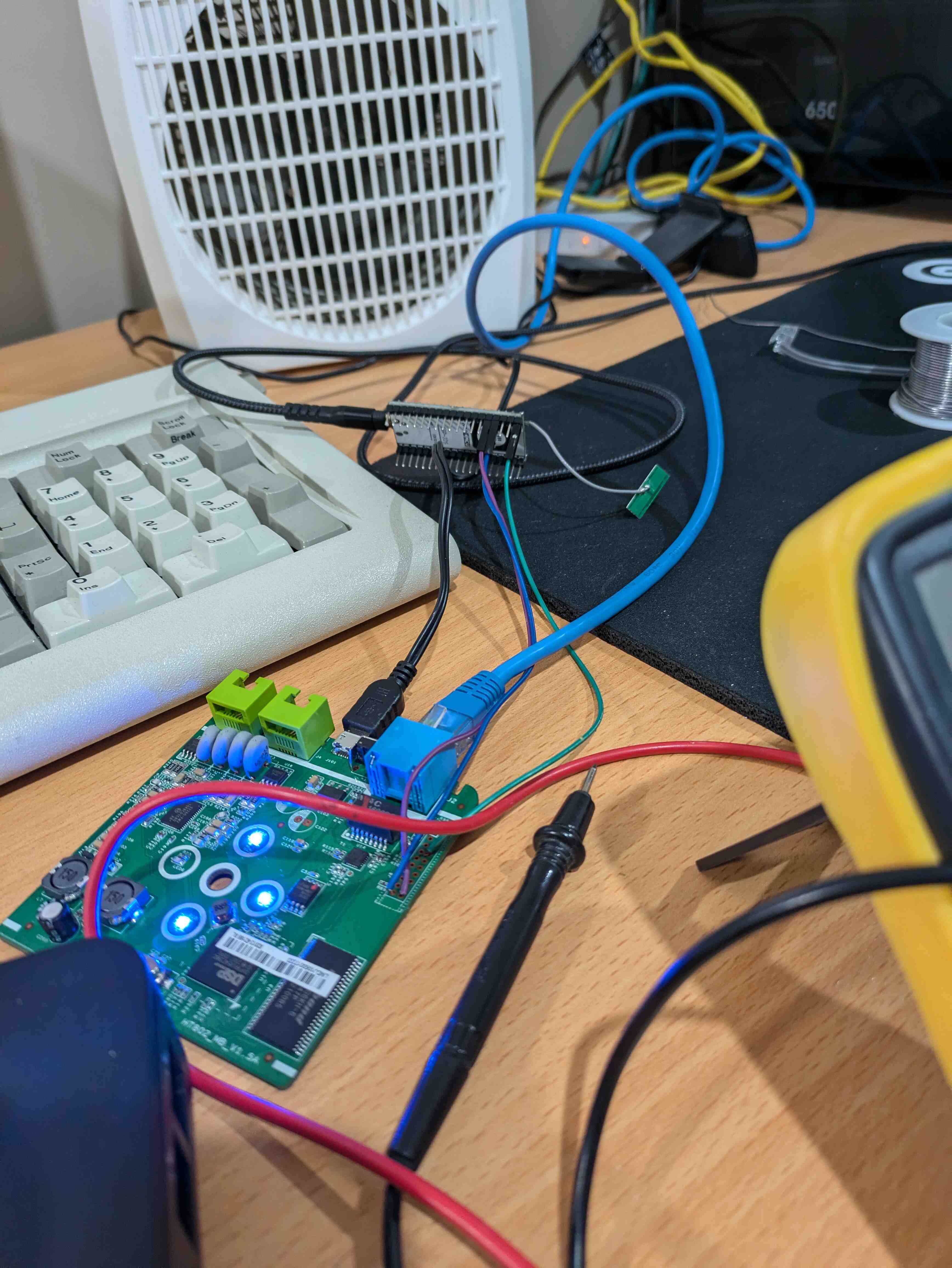
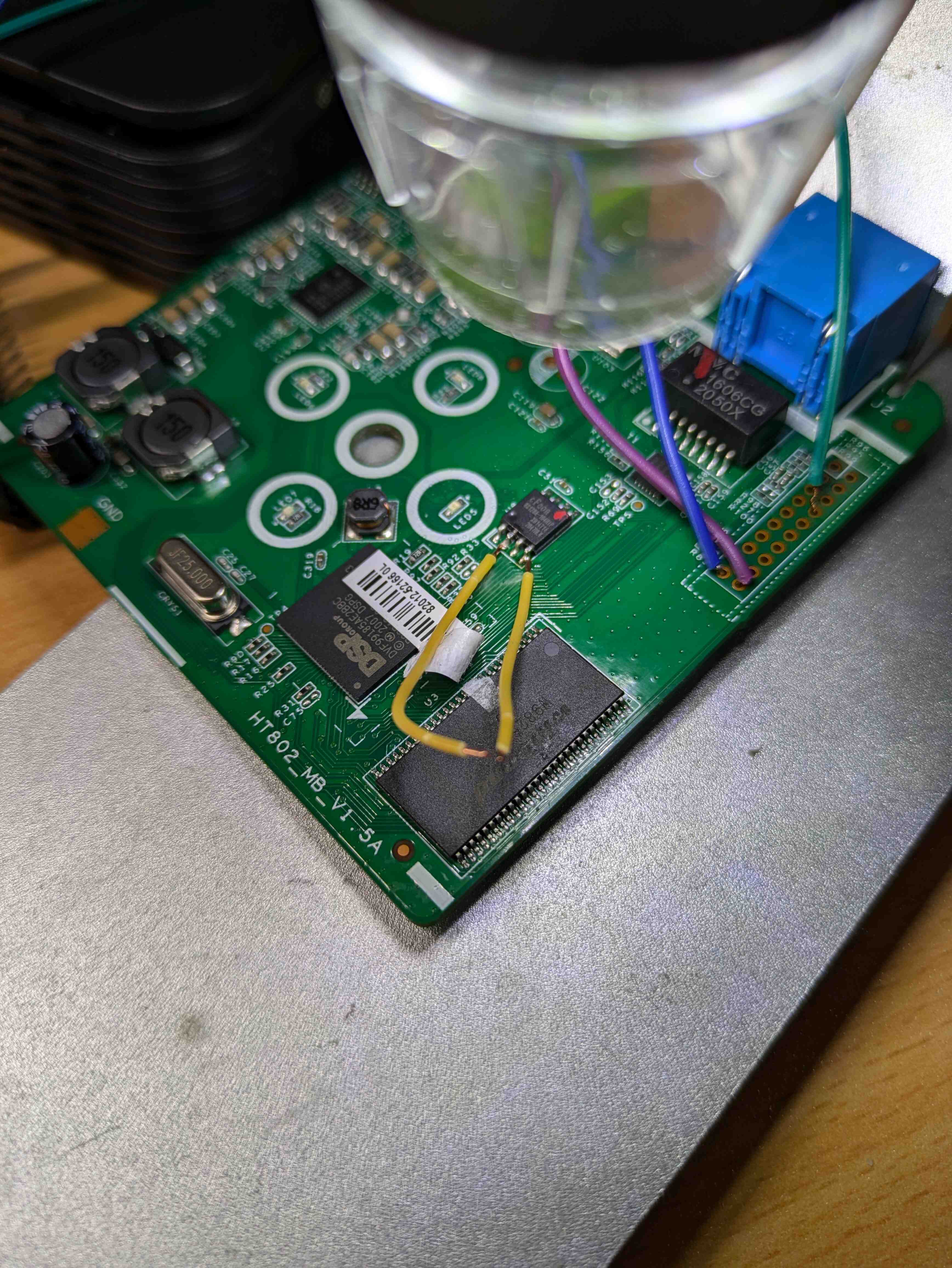
The length of my knowledge stops at this next idea. I could try glitching the storage to stop uboot from reading the kernel, hopefully dropping me into a shell in which I could boot the kernel with a console enabled, modify dropbear to provide a shell and win the game. This version of the HT802 uses a EN25Q16A-104HIP NOR flash chip. The idea is to ground the data out pin precisely when the kernel is being loaded. This will cause it to fail loading the kernel, and hopefully put me at a uboot prompt.
This was my setup for glitching this chip.
I found if I interrupt uboot itself being loaded from the chip, I get a message saying it is waiting for an xmodem image:
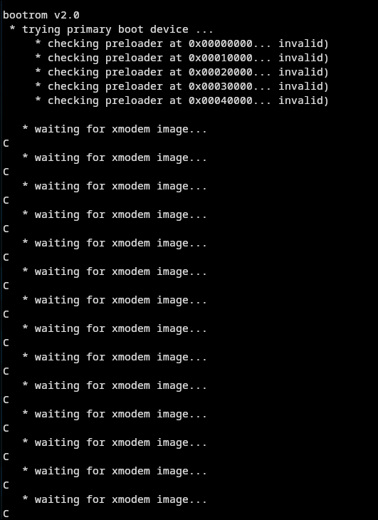
I tried sending it the firmware file over xmodem, but this didn't work. I honestly don't know much about what is expected to be uploaded and I didn't really investigate further.
Back to glitching the loading of Linux.. I was successful in preventing it from loading, however it just hung the system. I think uboot was compiled without any recovery environment. This is really unfortunate. If anyone has ideas on what to do next, I'd love to hear from you.
Back to the phones
It was time to figure out how exactly I am going to wire these phones. The HT802 will be in the room next to mine, so I am able to just run cable from my room into there, so that is no issue. Thw kitchen/living area is a bit harder. This property now has fiber internet, however it once had ADSL using the phone lines. There is an RJ12 port in the kitchen, so I investigated using that. I wasn't sure if the wiring was disconnected/cut when fiber was installed. So I put 9V on the line and found they are still connected to each other.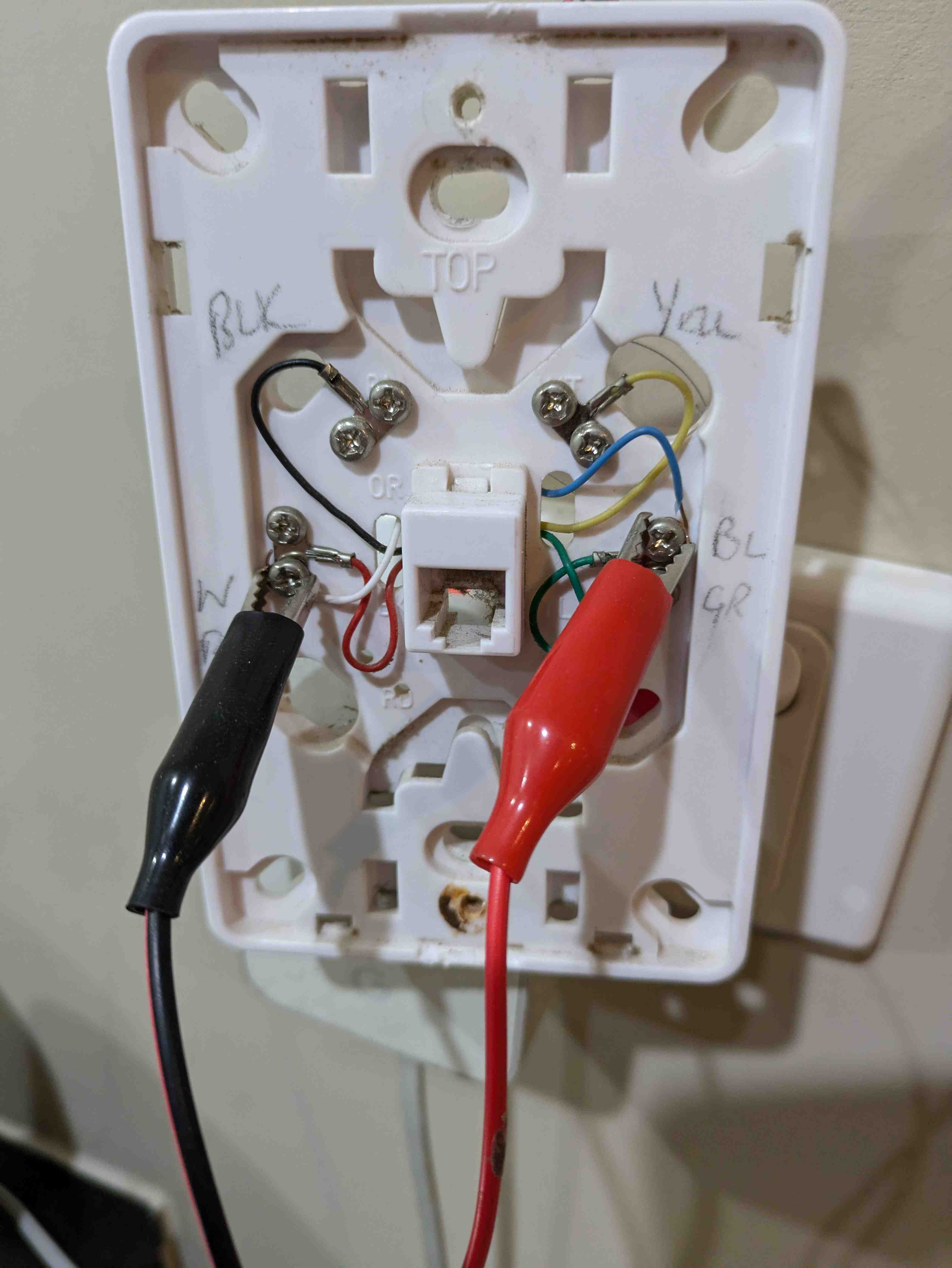
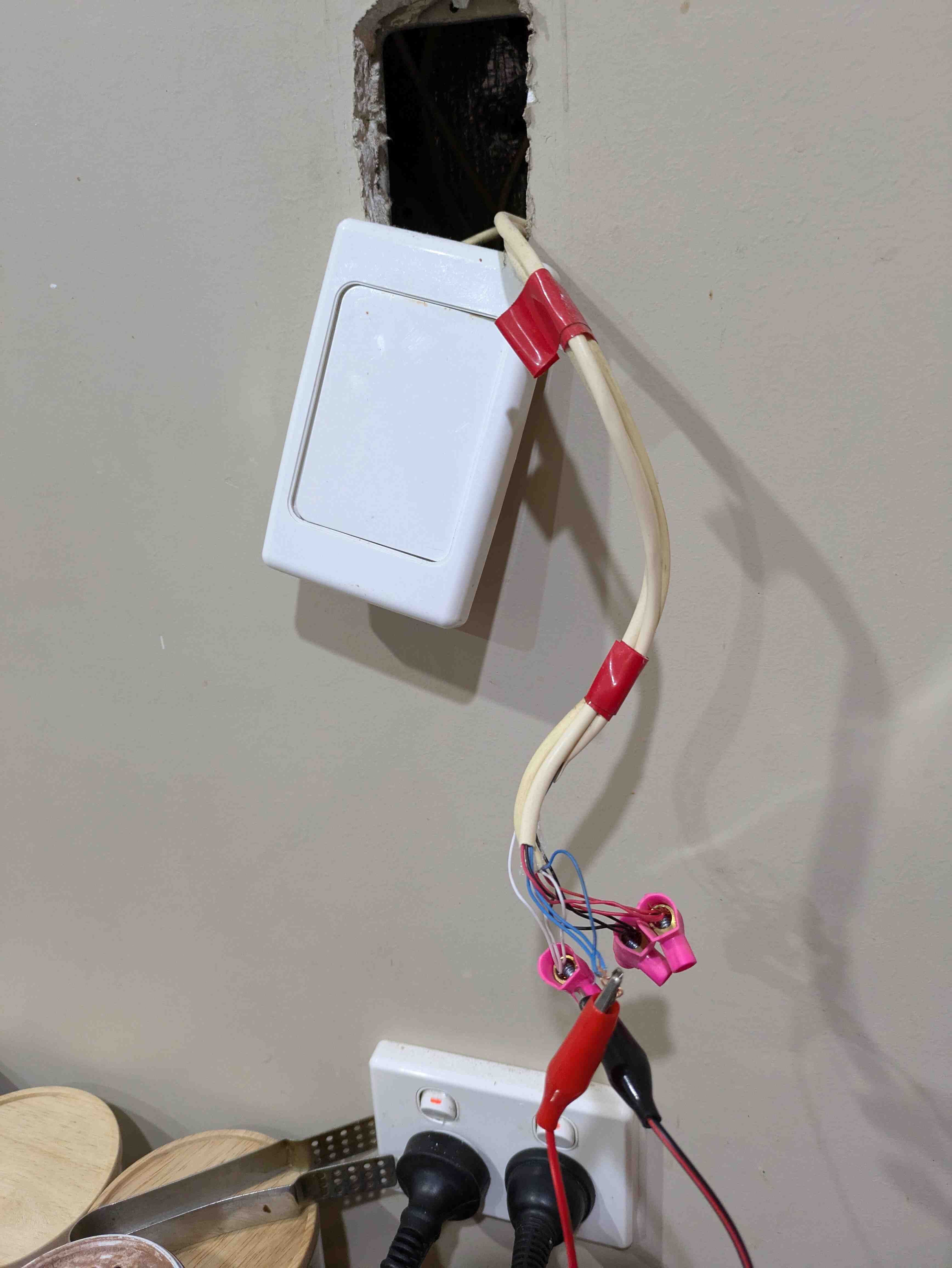
I also found two extra phone lines covered by a blank plate. Neat.
The other phone
I found a really attractive deal online for a Japanese imported 600-A2 handset. So I bought it. I knew nothing about this handset other than it was Japanese and black.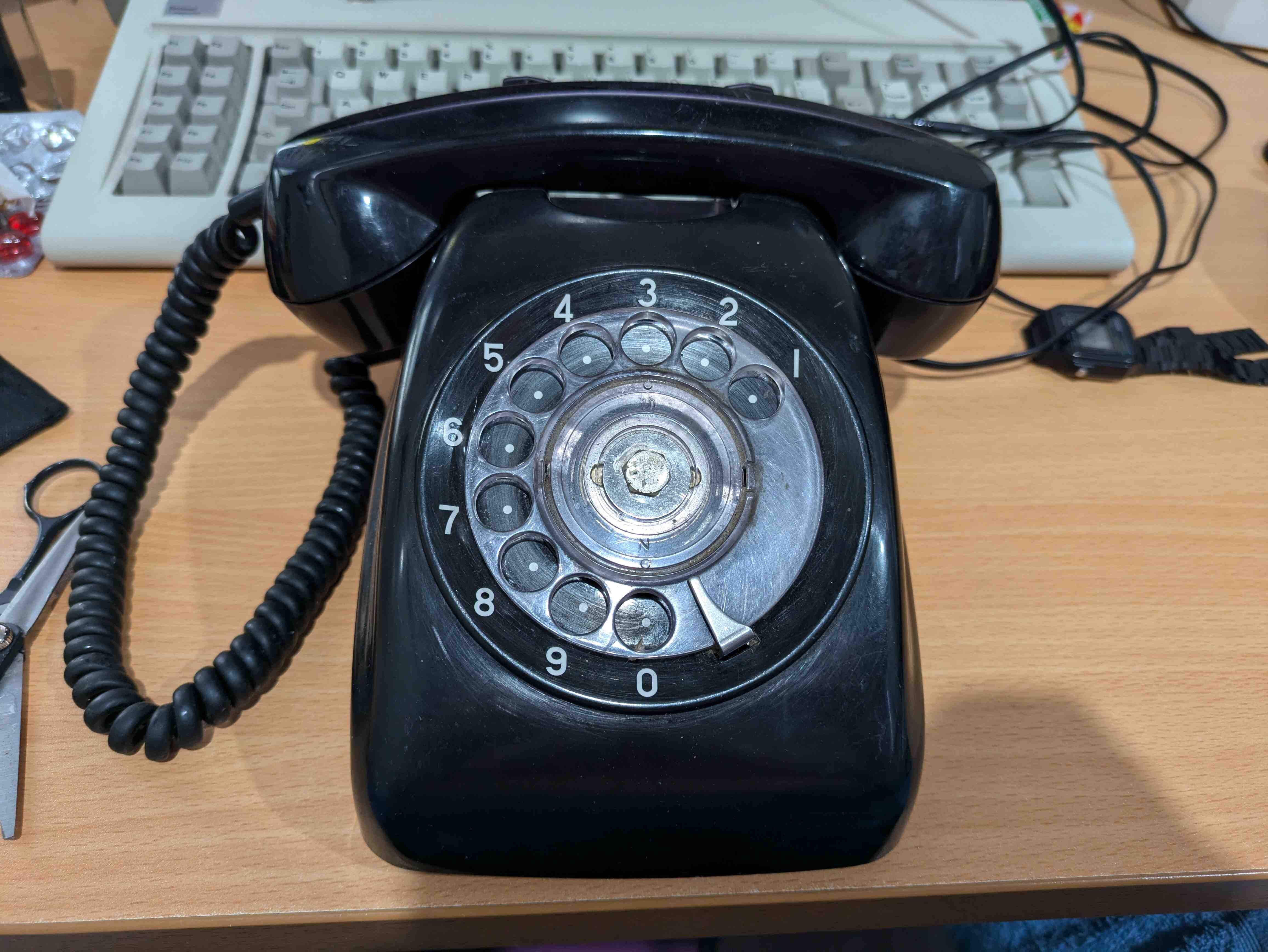
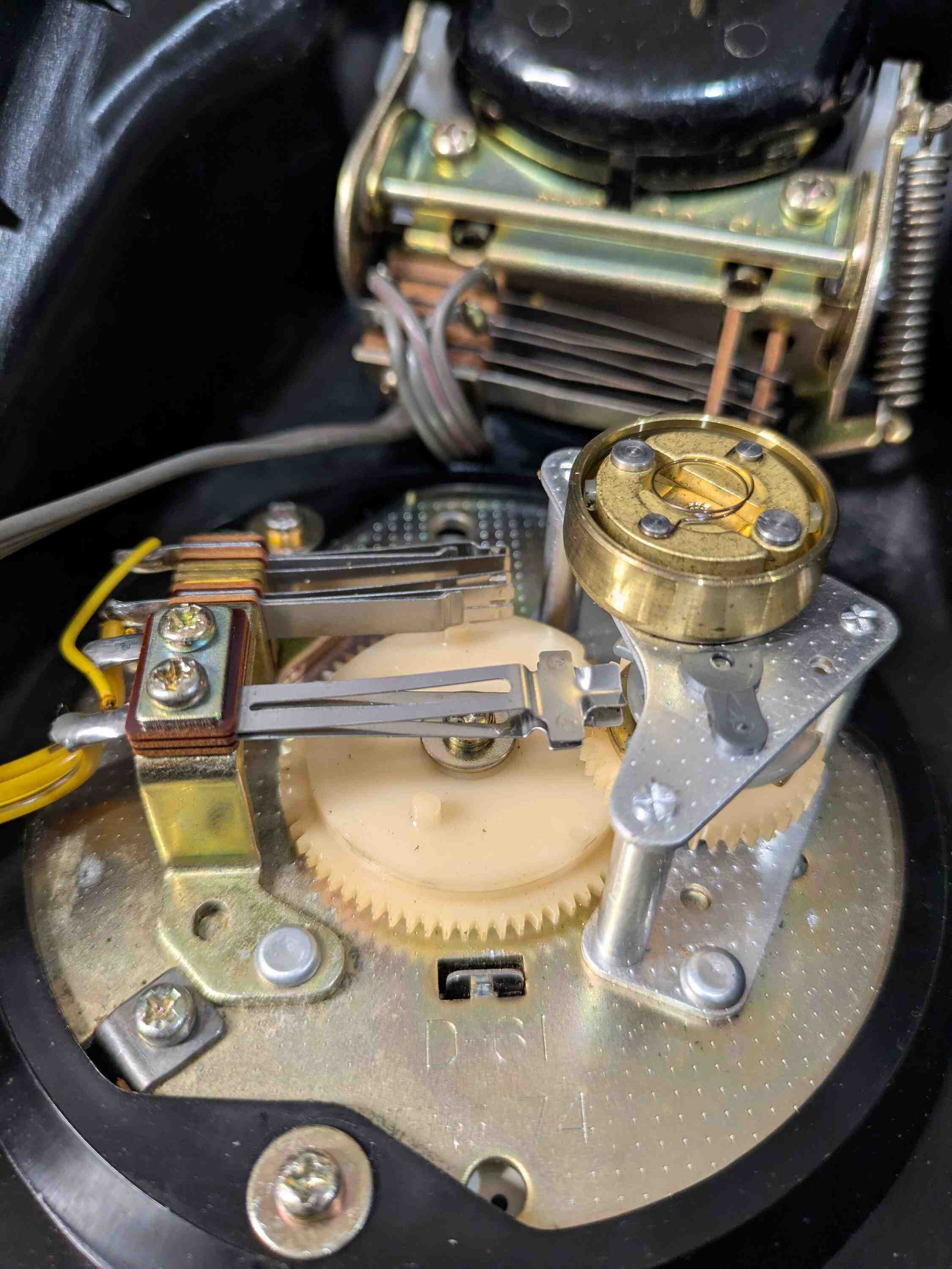
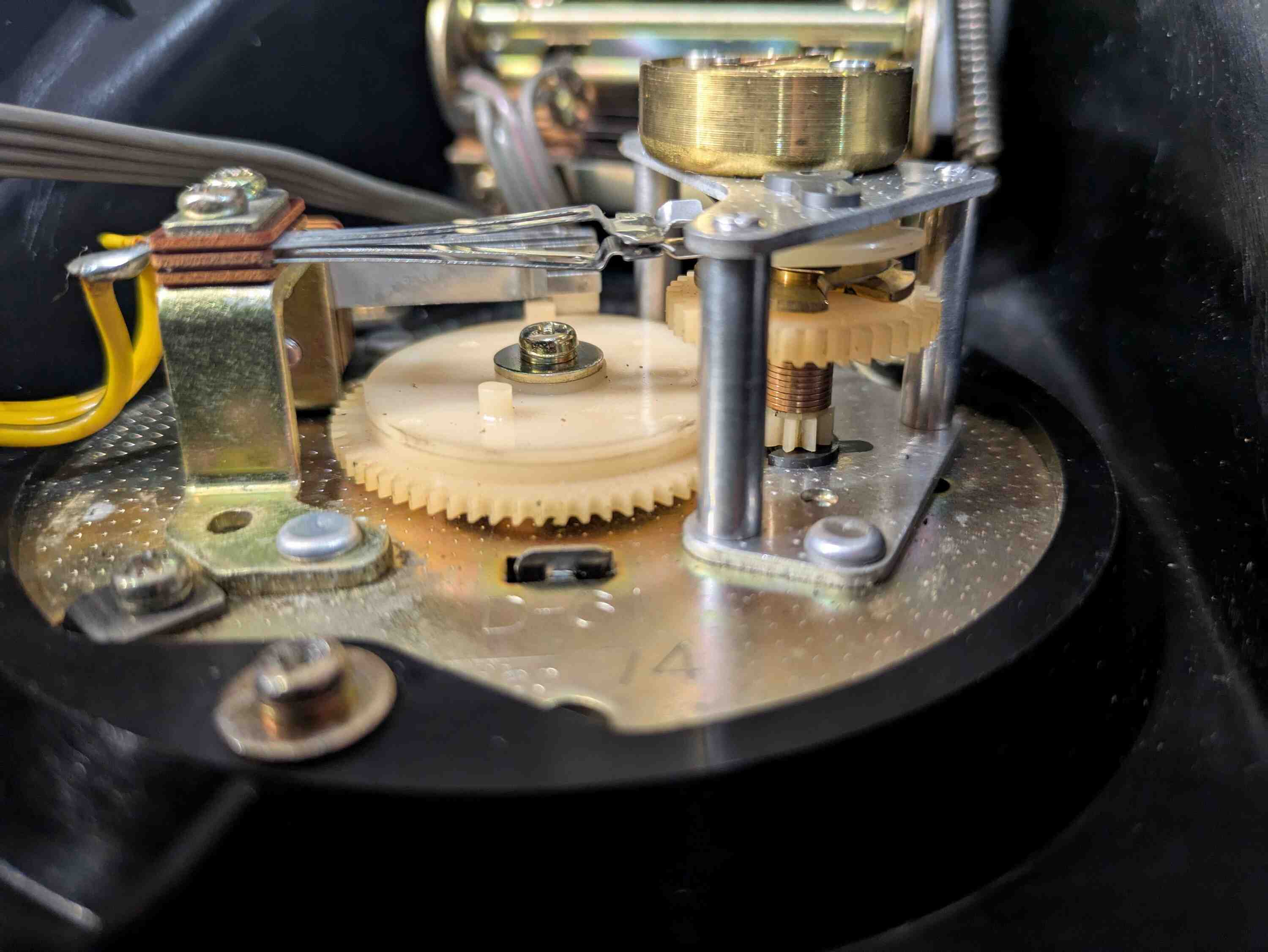
As it turns out, I managed to purchase quite a non-standard phone. I noticed the dial was really fast compared to my other phone. After some research, I found the 600-A1 has a 10PPS dial, while the A2 which I have, has a 20PPS dial. PPS stands for Pulses Per Second, the speed at which the dial pulses the phone line signaling the telephone provider. Cool, I thought, that will make dialing quicker. While true, something I didn't consider was whether or not my ATA would agree with the new fandangled fast dial. It turns out the HT802 does not in fact support 20PPS. As it turns out, 20PPS was only really known elsewhere in the world to be reserved for special phones used in the telephone exchanges and were not for end users, so commercial ATA devices do not support this. I turned to the Classic Rotary Phones Forum and opened this thread asking for some advice. These guys have been amazing, by the way. They helped me a lot. They seemed a bit confused too as to why this phone was 20PPS and I was quite concerned I'd not be able to use this phone. Through the forum I was informed that there is a spring known as a governer spring that controlled the braking mechanism in the dial. Seeing as my spring was removable I took it out and found that the dial now registered on my ATA, but was horribly slow.
This is the governer spring:
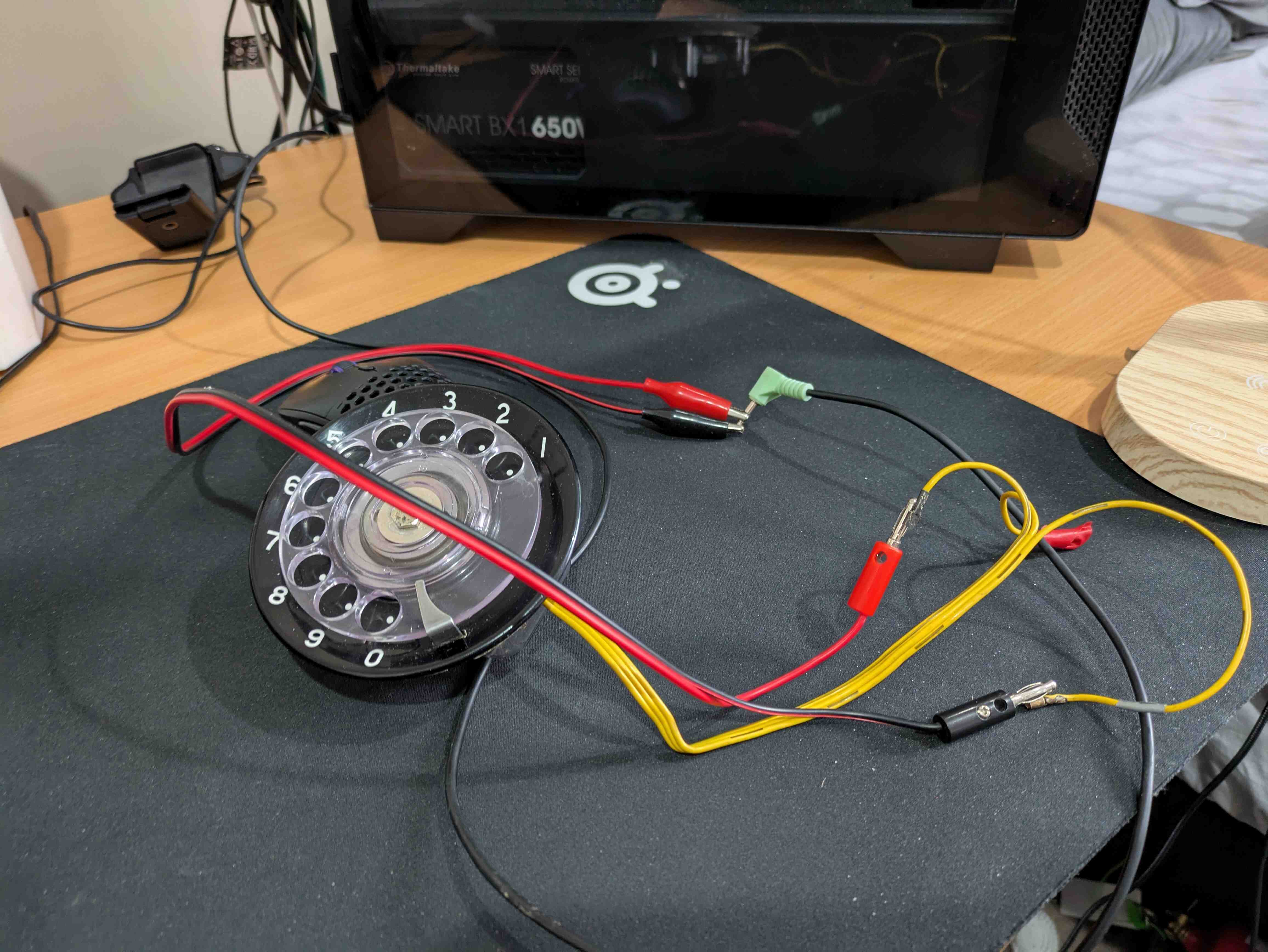
One of the users suggested that I properly measure the speed of the dial with and without the spring, then adjust it to be close enough to 10PPS. I was told to do this, I just need to connect the dial to an aux cable tip and ring, plug it into my microphone port and record dialing a 0. This shorts the cable ring and tip together causing pulses to be recorded in audacity. These pulses can then be used to calculate the PPS using a spreadsheet provided by the forum.
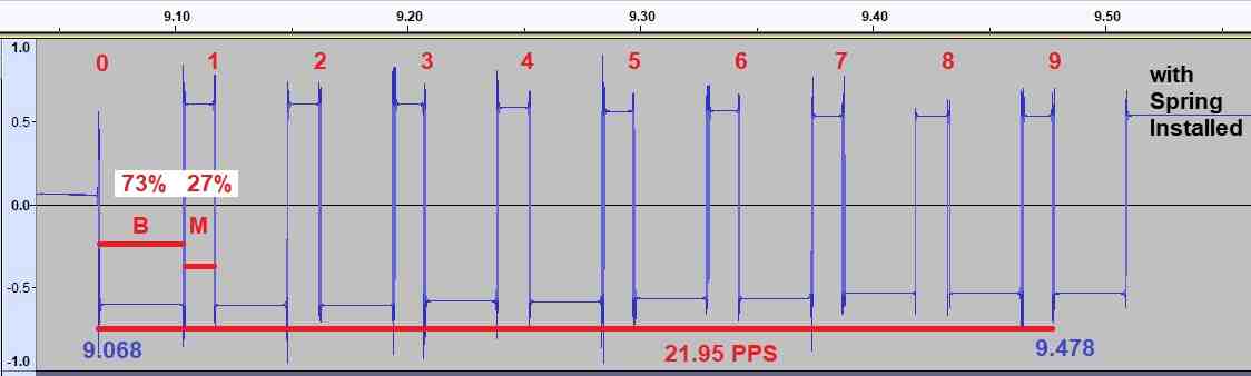
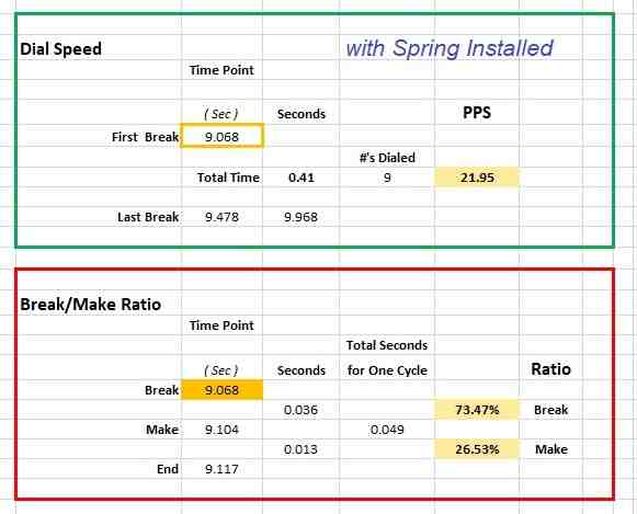
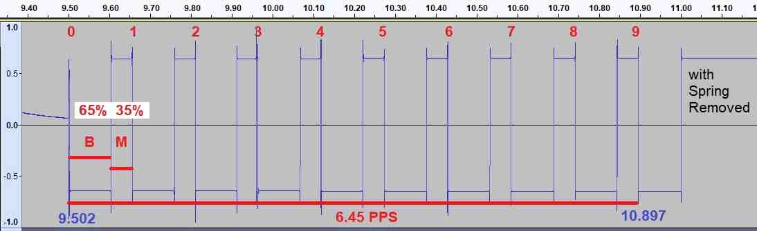
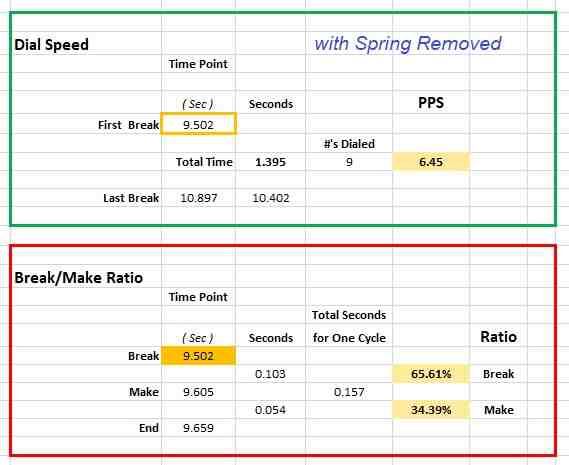
As it turns out, with the governer spring installed, my dial is 21.95PPS, and without it is 6.45PPS. Both of these numbers are far from the desired 10PPS. I have since spent a lot of time adjusting this spring to reach 10PPS but haven't got below 14PPS yet. So when not trying to modify it, I just keep the spring removed.
Having some fun
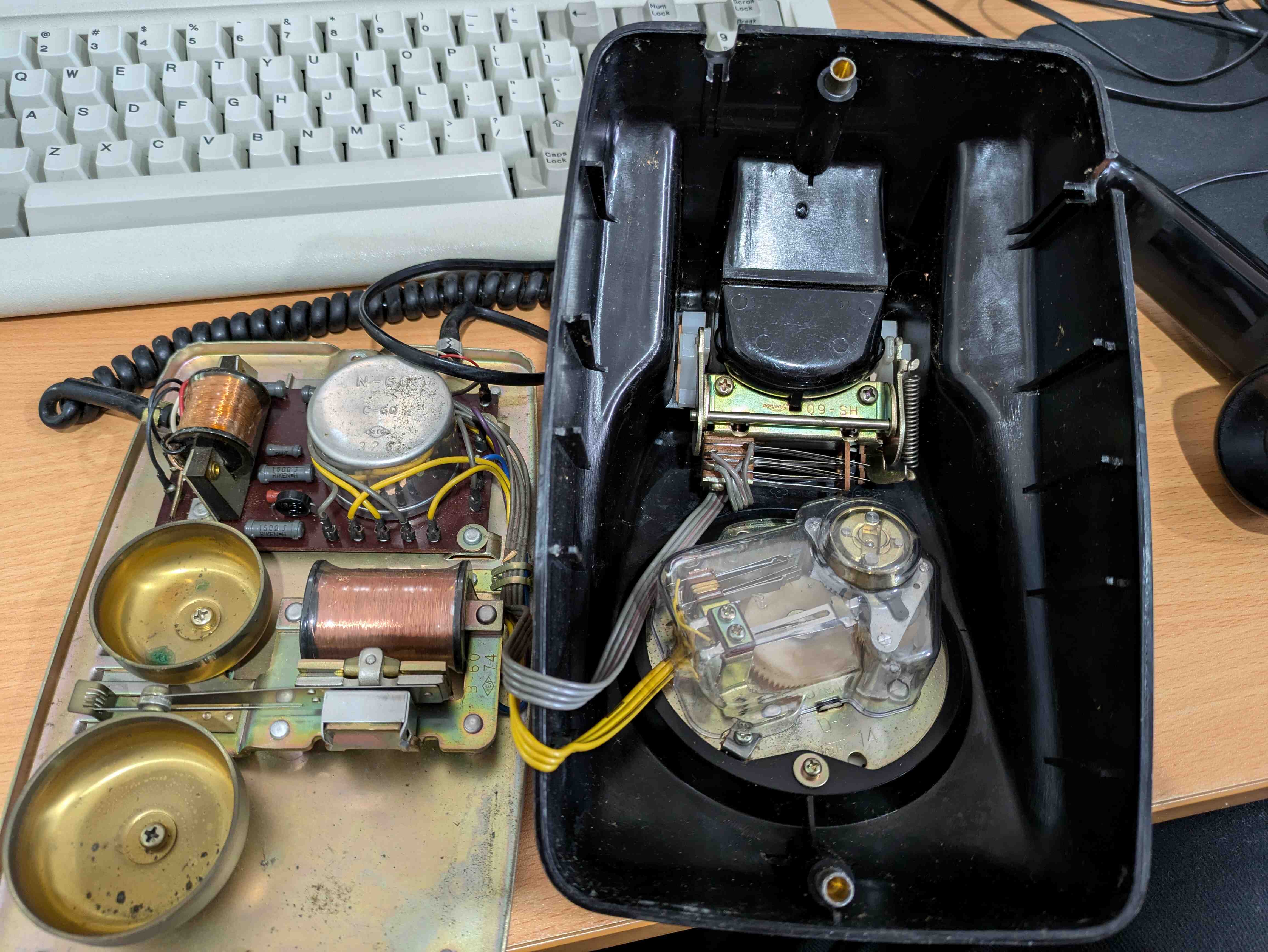
While I had one of my phones disassembled for modifications I thought it'd be a fun idea to see what I could do with the dial and handset.It's a little bit of a joke amongst my friend group that I have a terrible microphone. I shouldn't, I have an expensive wireless headset, but the mic on it isn't great. Plus the boom arm sags and goes away from my mouth. So I thought it'd be funny to hook the microphone up to my computer and talk using it. This is really simple, just attach the speaker wires to the tip and ring of an aux cable. I thought it was funny, but no one else did.
This is a recording taken using the handset:
My focus then moved to the dial. I thought it'd be neat to hook the dial up to a microcontroller. My first idea was to put an LED at each digit and light up the number dialed. This was cool but then I figured why not hook up a seven segment display. So I wired it up to an esp32 and roughly soldered on a seven segment display.
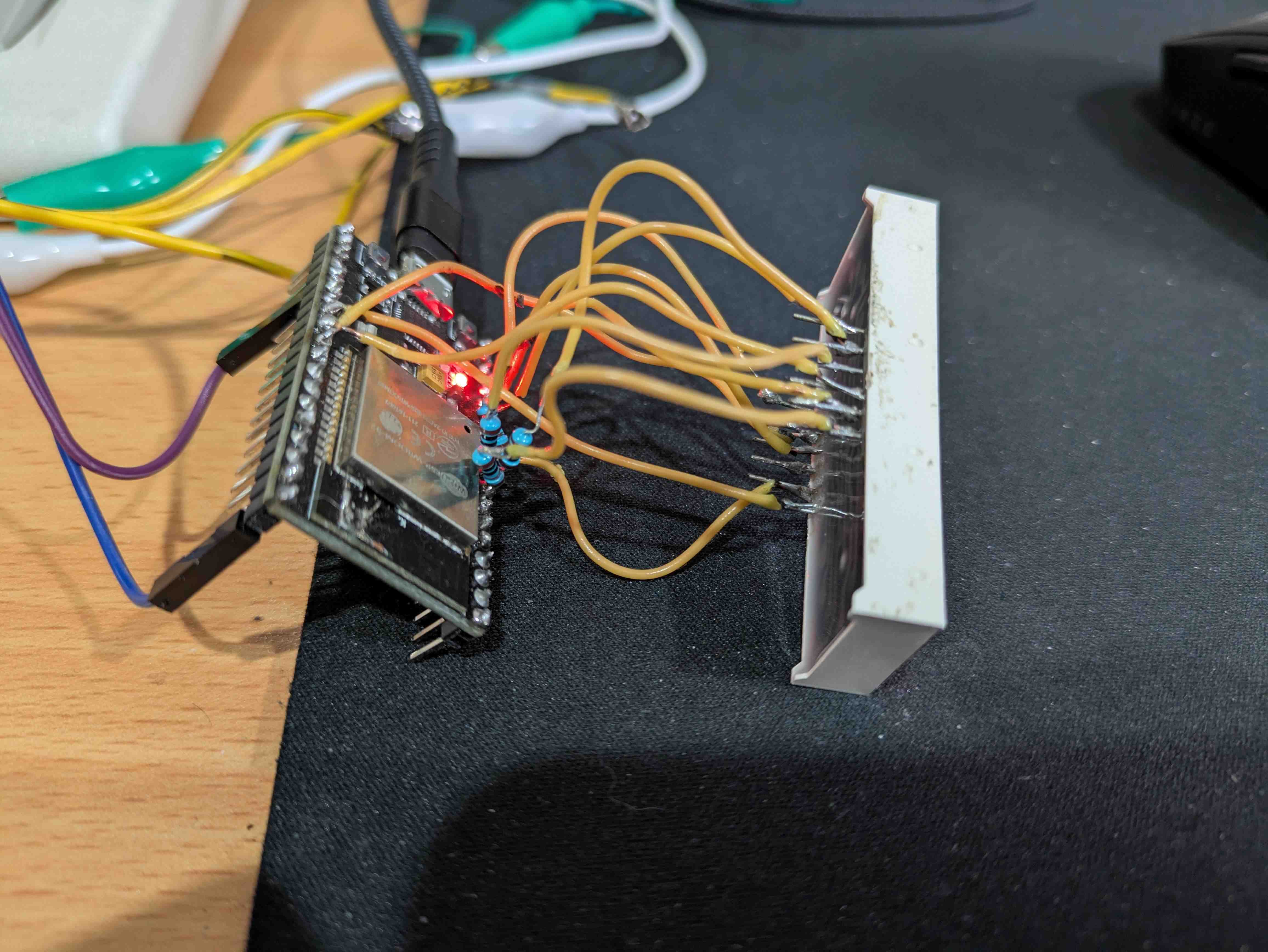
I then wrote some code to display the numbers dialed in a circular buffer of 4 digits.
This was really neat, I would love to make this a permanent toy.
I've become very interested in Counter-Strike in the last months again, so I thought it'd be a hilarious idea to use this as a keypad for selecting weapons in the game. The Reddit community thought this was interesting too. If you don't understand what is going on, I have bound each digit dialed to selecting a particular weapon or grenade.
I use a python script to read the incoming serial data from the esp32 and use uinput to press a virtual key.
Here is the C++ code the esp32 and the python script used:
#include <Arduino.h>
#include <RotaryDial.h>
#include "SevSeg.h"

TaskHandle_t rotaryTask;
TaskHandle_t displayTask;

// Buffer structure protected by mutex
struct {
  uint8_t digits[4] = {0, 0, 0, 0};  // Buffer for 4 digits
  uint8_t position = 0;               // Current position in buffer
  bool updated = false;               // Flag for new digit
} displayBuffer;

portMUX_TYPE bufferMux = portMUX_INITIALIZER_UNLOCKED;

SevSeg sevseg;

#define ROTARY_DIAL_PULSE_PIN 2
#define ROTARY_DIAL_TIMEOUT 3000
#define DISPLAY_BUFFER_SIZE 4

// Function to add digit to buffer
void addToBuffer(uint8_t digit) {
  portENTER_CRITICAL(&bufferMux);

  // Shift all digits left
  for(int i = 0; i < DISPLAY_BUFFER_SIZE - 1; i++) {
    displayBuffer.digits[i] = displayBuffer.digits[i + 1];
  }

  // Add new digit at rightmost position
  displayBuffer.digits[DISPLAY_BUFFER_SIZE - 1] = digit;
  displayBuffer.updated = true;

  portEXIT_CRITICAL(&bufferMux);
}

// Function to convert buffer to display number
int bufferToNumber() {
  int number = 0;
  for(int i = 0; i < DISPLAY_BUFFER_SIZE; i++) {
    number = number * 10 + displayBuffer.digits[i];
  }
  return number;
}

// Rotary dial task
void rotaryDialTask(void * parameter) {
  unsigned long lastdigit = 0;
  bool newline = true;

  for(;;) {
    if(RotaryDial::available()) {
      int in = RotaryDial::read();

      // Only accept valid single digits
      if(in >= 0 && in <= 9) {
        addToBuffer(in);
        Serial.printf("%d\n", in);
      }

      lastdigit = millis();
      newline = false;
    } else {
      if(!newline && millis() - lastdigit > ROTARY_DIAL_TIMEOUT) {
        Serial.println(" OK");
        newline = true;
      }
    }
    vTaskDelay(1);
  }
}

// Display task
void displayTask_fn(void * parameter) {
  int displayNumber = 0;

  for(;;) {
    portENTER_CRITICAL(&bufferMux);
    if (displayBuffer.updated) {
      displayNumber = bufferToNumber();
      displayBuffer.updated = false;
    }
    portEXIT_CRITICAL(&bufferMux);

    sevseg.setNumber(displayNumber);
    sevseg.refreshDisplay();
    vTaskDelay(2);
  }
}

void setup() {
  Serial.begin(115200);

  // Initialize rotary dial
  pinMode(ROTARY_DIAL_PULSE_PIN, INPUT_PULLUP);
  RotaryDial::setup(ROTARY_DIAL_PULSE_PIN);

  // Initialize display
  byte numDigits = 4;
  byte digitPins[] = {32, 33, 25, 26};
  byte segmentPins[] = {13, 12, 14, 27, 16, 17, 5, 4};

  bool resistorsOnSegments = false;
  bool updateWithDelays = false;
  bool leadingZeros = true;  // Changed to true to show all digits
  bool disableDecPoint = true;

  sevseg.begin(COMMON_CATHODE, numDigits, digitPins, segmentPins,
               resistorsOnSegments, updateWithDelays, leadingZeros, disableDecPoint);
  sevseg.setBrightness(90);

  // Create rotary dial task on core 0 with highest priority
  xTaskCreatePinnedToCore(
    rotaryDialTask,
    "RotaryTask",
    10000,
    NULL,
    configMAX_PRIORITIES - 1,
    &rotaryTask,
    0
  );

  // Create display task on core 1 with lower priority
  xTaskCreatePinnedToCore(
    displayTask_fn,
    "DisplayTask",
    10000,
    NULL,
    1,
    &displayTask,
    1
  );

  Serial.println("Setup complete");
}

void loop() {
  vTaskDelay(100);
}
import serial
import time
from evdev import UInput, ecodes as e


ser = serial.Serial('/dev/ttyUSB0', 115200)
time.sleep(2)


key_map = {
    '0': e.KEY_A,
    '1': e.KEY_1,
    '2': e.KEY_2,
    '3': e.KEY_3,
    '4': e.KEY_Z,
    '5': e.KEY_X,
    '6': e.KEY_C,
    '7': e.KEY_V,
    '8': e.KEY_I,
    '9': e.KEY_J
}


ui = UInput()

try:
    while True:
        if ser.in_waiting > 0:
            data = ser.readline().decode('utf-8').strip()
            if data in key_map:
                print(f"Received: {data}, Pressing: {key_map[data]}")
                # Simulate key press and release
                ui.write(e.EV_KEY, key_map[data], 1)
                ui.write(e.EV_KEY, key_map[data], 0)
                ui.syn()
        time.sleep(0.1)

except KeyboardInterrupt:
    print("Program terminated")

finally:
    ser.close()
    ui.close()
Making the phones call each other
At this point, I have both phones functional, and both connected to the ATA. Now I have to configure the ATA itself. There are a metric boatload of options available in this ATA, I know what barely any of them do. Following some guides online, I needed to give each FSX port its own port number on the device to listen on. I then setup a dial plan on each phone to allow calling 101, or 102 respectively to dial the ATA's IP address on the configured port for each phone.{ <102=*47127*0*0*1*5062> | 100 | 101 | 111 | 112 | 155 | 195 | 999 | 116xxx | 116111 | 116123 | 118xxx | 1471 | 157[1-2] | 08001111 | 0845464x | 0[1235789]xxxxxxxxx | 00xxx. | 1002 | x+ | \+x+ | *x+ | *xx*x+ }
I don't understand this, I will be surprised if you do either, but this is the dial plan required to allow dialing a direct IP address. I can understand the beginning, but not the rest of it. I'm not sure I want to.It works! Hooray! But wait, the black phones ringer sounds horrible..
I took the black phone apart again and adjusted the ringer.
I will leave you with the wonderful ringing I desired from the start of this project:
What did the person I live with think?
We have used the phones a few times, but they still just yell out my name or knock on my door.. But it was fun, a huge success!

Thought process of a programming problem
3/11/2024
For my LED matrix sign project I store all the customisations and text in the ESP32's NVRAM. I do this in a very naive way of writing raw memory directly to the NVRAM packed into two data structures. This has one very big flaw, if I change the internal layout of these structures in any way, the memory in NVRAM will no longer be valid.
Before making any changes to the code, this is the layout of the structure in question:
struct
{
	int pos;
	int brightness;
	char cssid[256];
	char cpassword[256];
	char date[32];

} globalconf;
This struct contains all the configuration settings that may be used globally.Specifically for this, we're interested in the brightness integer.
I wanted to add automatic brightness adjustment depending on the rooms current light level. I do this using an LDR. to achieve this, I needed a way to store whether or not the auto brightness feature is enabled or not.
My first naive implementation seen in this commit simply added more fields to the globalconf structure.
This worked, however it made my the current settings stored in the NVRAM incompatible. This is because the memory size of the structure changed by 16 (or so) bytes. When this memory is read into the new structure from NVRAM, it is incorrect.
I had to come up with a new solution, so I did some brainstorming and made notes in chat. I am going to paste those logs here and explain at the end the final solutions.
I could just pack that autobrightness bool into the brightness int as it is literally 1 bit required
then i'd not break the globalconf structure
the value of brightness is literally 0-15
so i could use the MSB to store the bool
i could do:
brightness |= autoBrightness ? (brightness | 0b10000000) : (brightness & 0b01111111);set the MSB if autobrightness is true, otherwise unset the MSB
then when i read the brightness later i need to read it like:
(brightness & 0b01111111)to ensure it is unset
or i KISS and leave it as is
OR i do the smarter thing actually
create a bit field with the same size as an int and do this built in
a bitfield lets you assign certain bits to certain values in a single packed bit of memory
struct brightness
{
    unsigned int autoBrightness : 1;
    unsigned int brightness : 4;
    unsigned int RESERVED : 3;
}
this will give me 3 bits to play with laterthis will use 1 byte of memory
brightness is 0-15 so 4 bits is plenty (can count to 15)
so i get MORE features and use 3 bytes less (as an int is 4 bytes)
but actually... i need to use all 4 bytes to not break my current memory structure
so really i need to do:
struct brightness
{
    unsigned int autoBrightness : 1;
    unsigned int brightness : 4;
    unsigned int RESERVED : 27;
}
to use all 32 bits of an int
Essentially, as seen in this commit, I simply added a struct bitfield the same size as the fields it replaces.
struct brightness
{
    unsigned int autoBrightness : 1;
    unsigned int brightness : 4;
    unsigned int RESERVED : 27;
};

struct
{
	int pos;
	struct brightness brightness;
	char cssid[256];
	char cpassword[256];
	char date[32];

} globalconf;
and gives me 27 bits later on to play with.


Downlights, Matter, Thread and Home Assistant
6/10/2024
I recently purchased a couple nanoleaf Essentials downlights to replace the ones in my room. I specifically chose these downlights as they support Matter over Thread. Matter is a communication protocol currently being implemented as another attempt at a standard for communication between hardware devices. Thread is a wireless networking technology being implemented to achieve the saame result. Matter can communicate over other networks as it is just a protocol, but a thread network requires special hardware.
I chose to purchase these from smarthome.com.au who happen to be relatively local. I went to their office to pick up my online purchase and found them very welcoming and helpful. The office felt like their loungeroom.
Ultimately, my plan was to finally setup Home Assistant and start using so called smart devices in a free and local way. There is not much in the way of online documentation for a lot of Matter/Thread devices, especially a relatively niche downlight, so most information was about nanoleaf's other products. Others require the device first be initialised in their Android software. They are setup via Bluetooth first, then Thread network support is enabled through the application.
Setting the devices up in the nanoleaf software did not go well. Recently a friend of mine gave me a Pixel 8a, finally a decent device with a modern bluetooth implementation. But the nanoleaf software refused to find any Thread networks on this phone. This is weird as the Thread networking is done on the downlight itself. It worked on a family members Samsung phone, which is much older than my device. No Matter, it worked in the end.
Now I needed Home Assistant running. I am currently running their provided OS image in kvm. To provide the VM direct access to the LAN without NATing, I gave the VM a Macvtap interface and I use the NAT interface for host->guest communication. Home Assistant conveniently listens on all interfaces. Obviously, as the Thread network requires special hardware, I also needed a device the VM can use to communicate. I chose to purchase the Home Assistant Connect. This USB dongle supports both Zigbee and Thread, however without very early firmware, only one or the other can operate at a time. I figured a Home Assistant specifically developed dongle would be the safer bet, even though it probably wont work on both networks yet. I only have Thread devices right now. I also gave it a Bluetooth dongle for a temperature sensor I planned to add as well.
I set Home Assistant up to be a Thread border router using the Open Thread Border Router integration, then setup both the Matter and Thread integrations following their documentation. Now it was time to add the devices to Home Assistant. This was a huge pain as Home Assistant refused to find the devices anywhere and I knew of no way to ensure my border router was working correctly and the other integrations were operating too. after hours and many threads read, I found I needed to sync Thread credentials by going into Settings->Companion app->Troubleshooting(!!)->Sync Thread credentials. After this the devices appeared and I was able to add them. Also, by the way, this all has to be done on a phone running the Home Assistant application. It cannot be done with the web UI.
Currently I have my lights and a Bluetooth Xiaomi Mijia temperature sensor hooked up to Home Assistant. I also have my LED Matrix sign controller software available in Home Assistant to keep it all in one place. That Matrix sign is in deserving of its own post, but you can see it in the image below. I am also utilising the Home Assistant API too get data from the temperature sensor and display it on my Matrix display.
I have moved house 4 times since last posting images, so here is a current one with the lights in action.


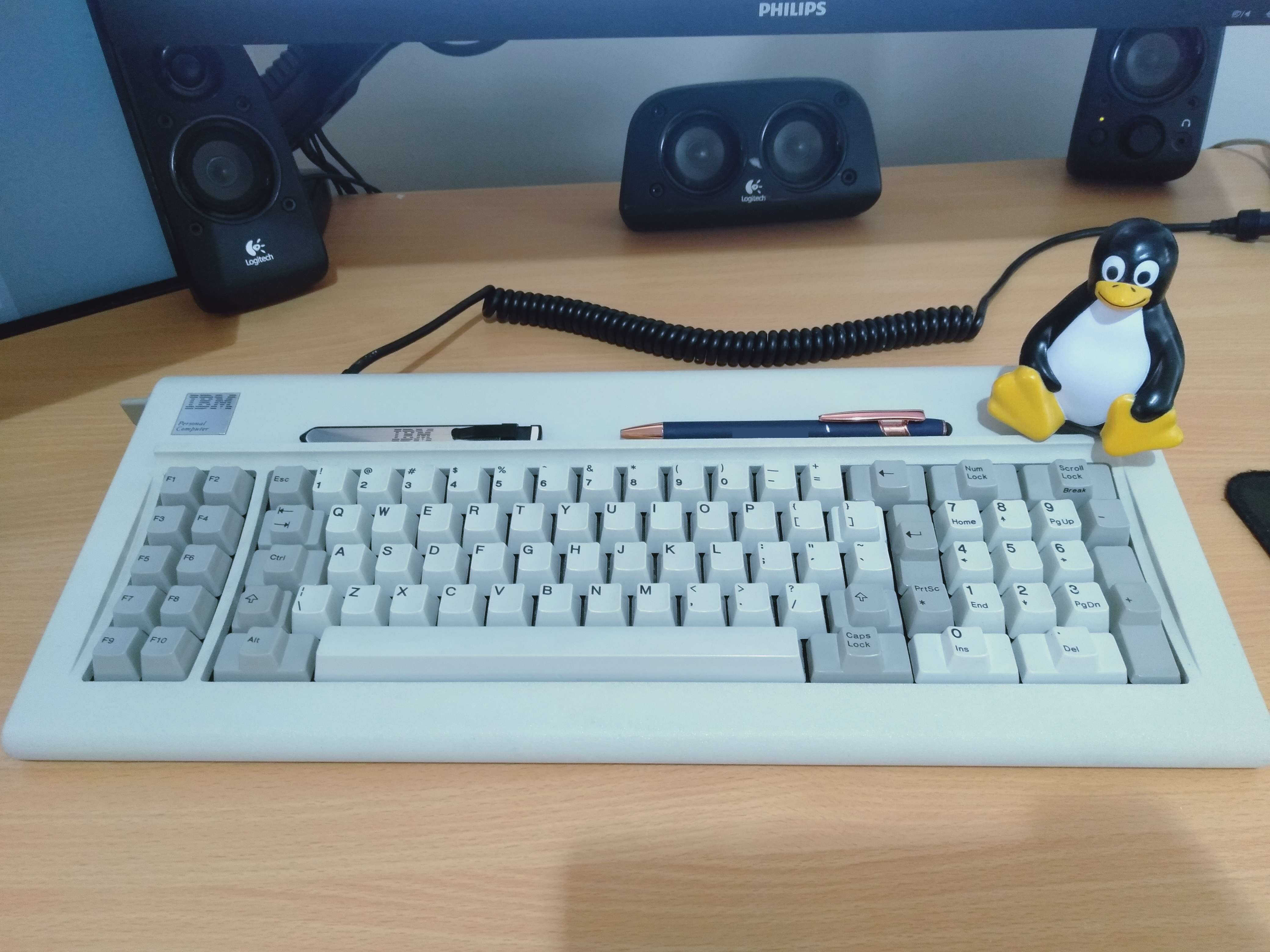
IBM Model F XT
27/09/2024
A little bit ago I acquired an IBM Model F XT in quite good condition. It has no damage internal or external, both feet and handles are present. I just had to replace the feet with some of my own cork.
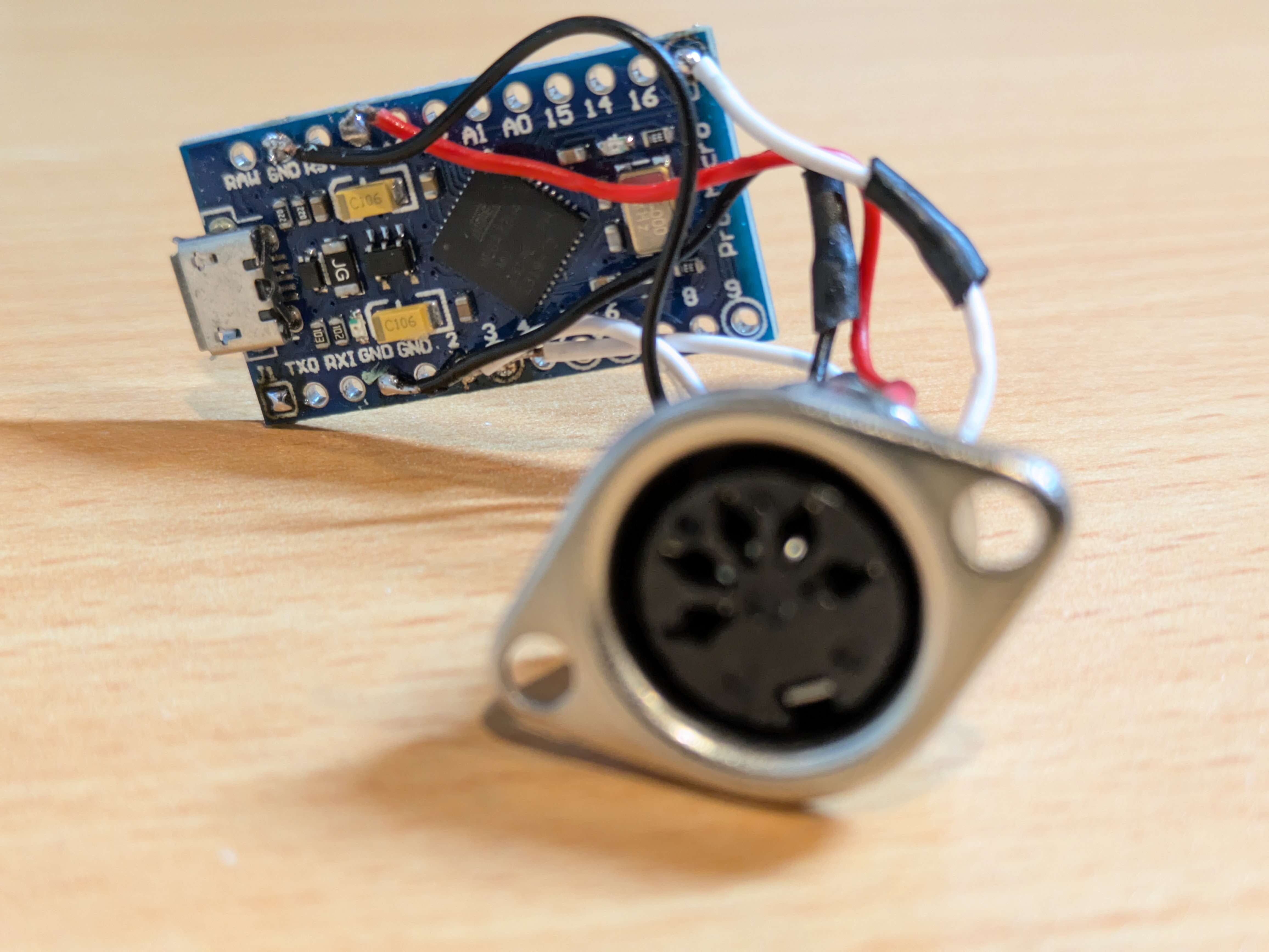
I also had to create an adapter to convert the PS/2 XT format to something a modern system can understand. This cannot be done with most active or passive converters. So I made one using a Pro Micro microcontroller running Soarer's Converter firmware and a female PS/2 connector.
I use this as my main keyboard for everyday tasks and games. As this keyboard is not made using a matrix there is no key rollover issues, so unlike the Model M, it is great for gaming (in my opinion). The layout is a bit hard to get used to though.


Inside a Powerpal
7/09/2024
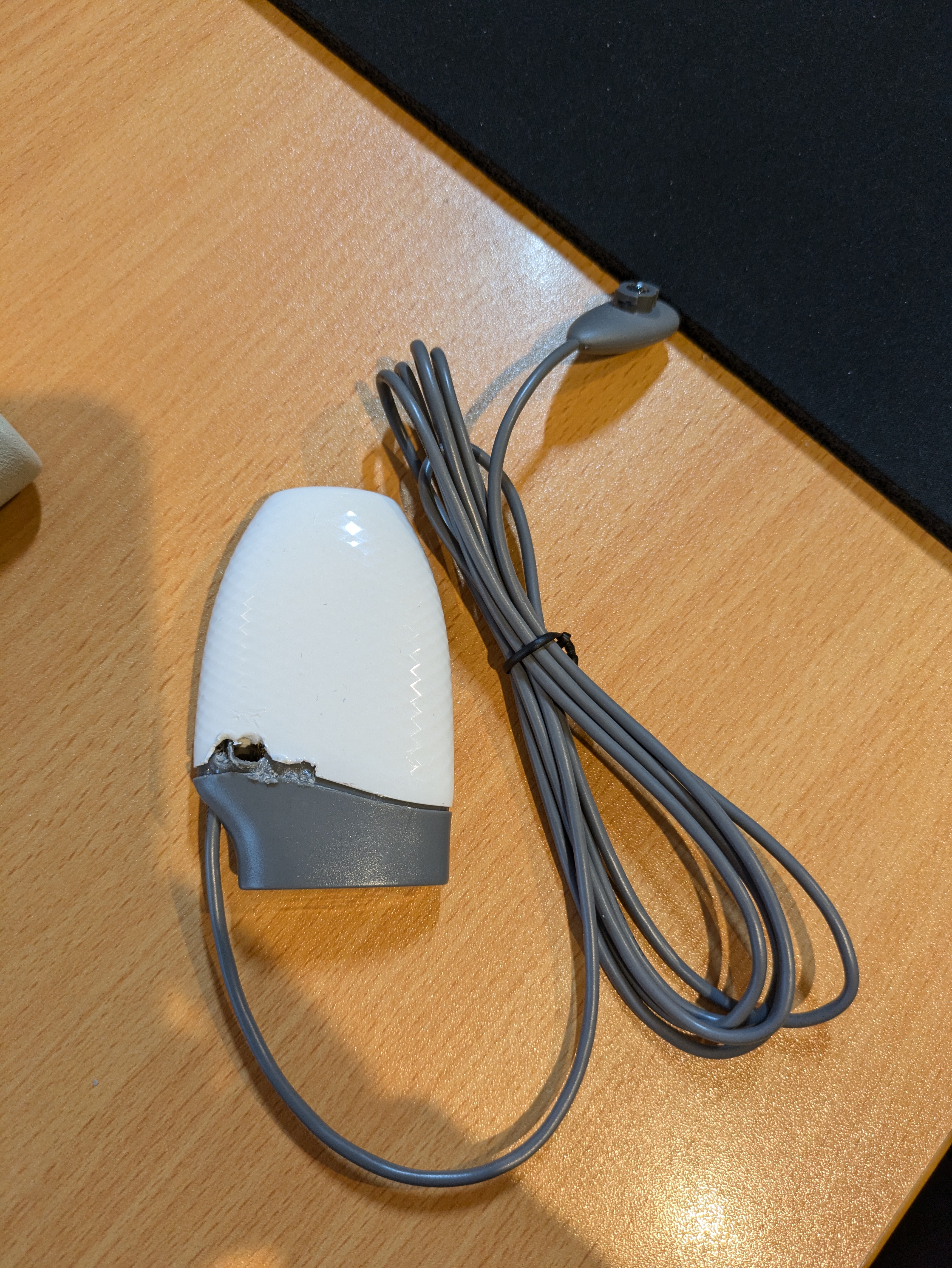
I have a spare Powerpal sitting around. Powerpal is a simple energy monitoring device you install on your meter box, it works by counting the flashing rate of an LED. Simple and effective.
I thought it'd be cool to see what is inside.
This casing is welded shut and has non-replacable batteries. So opening it is destructive to the casing, but it still slides back together.
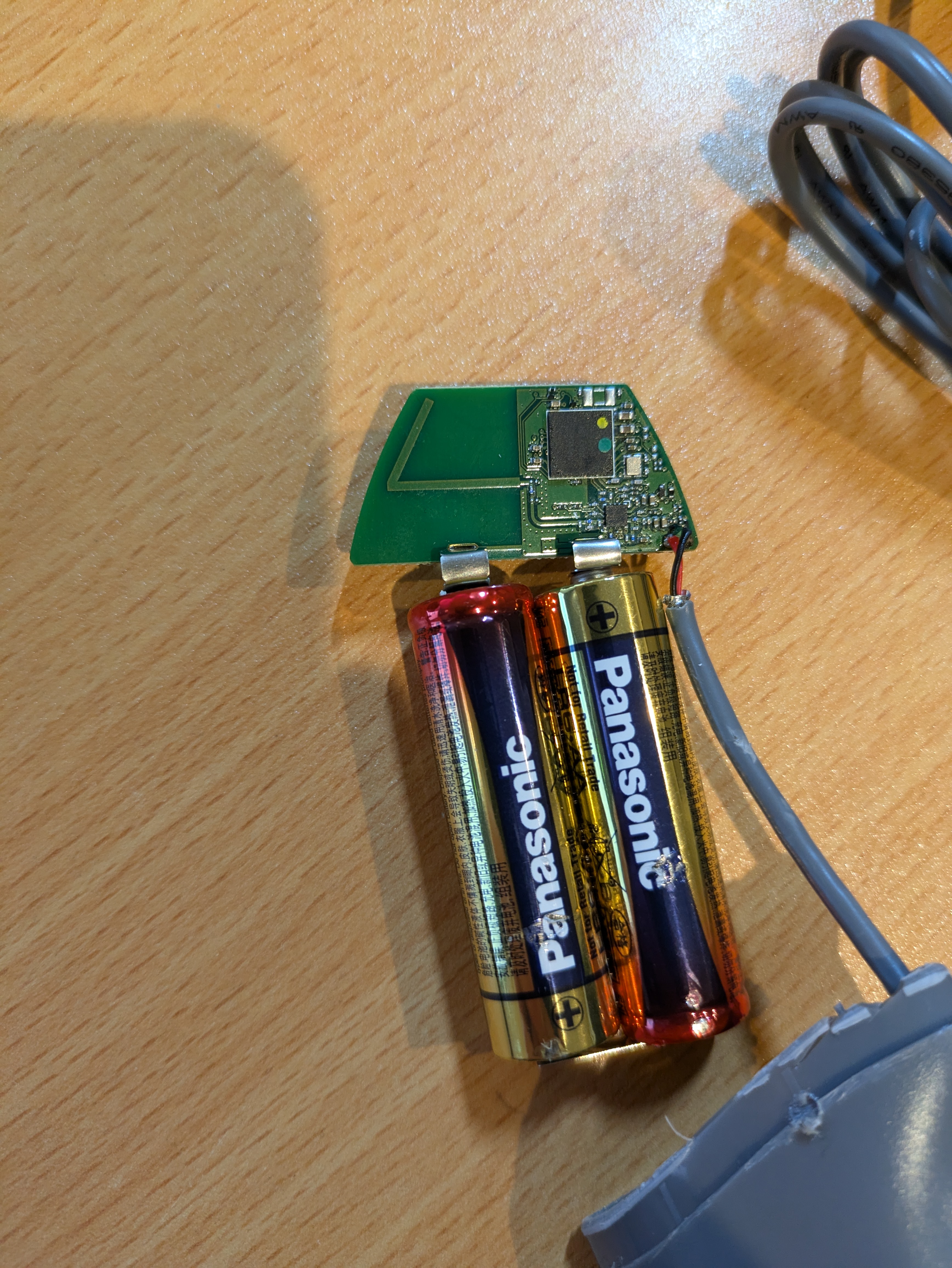
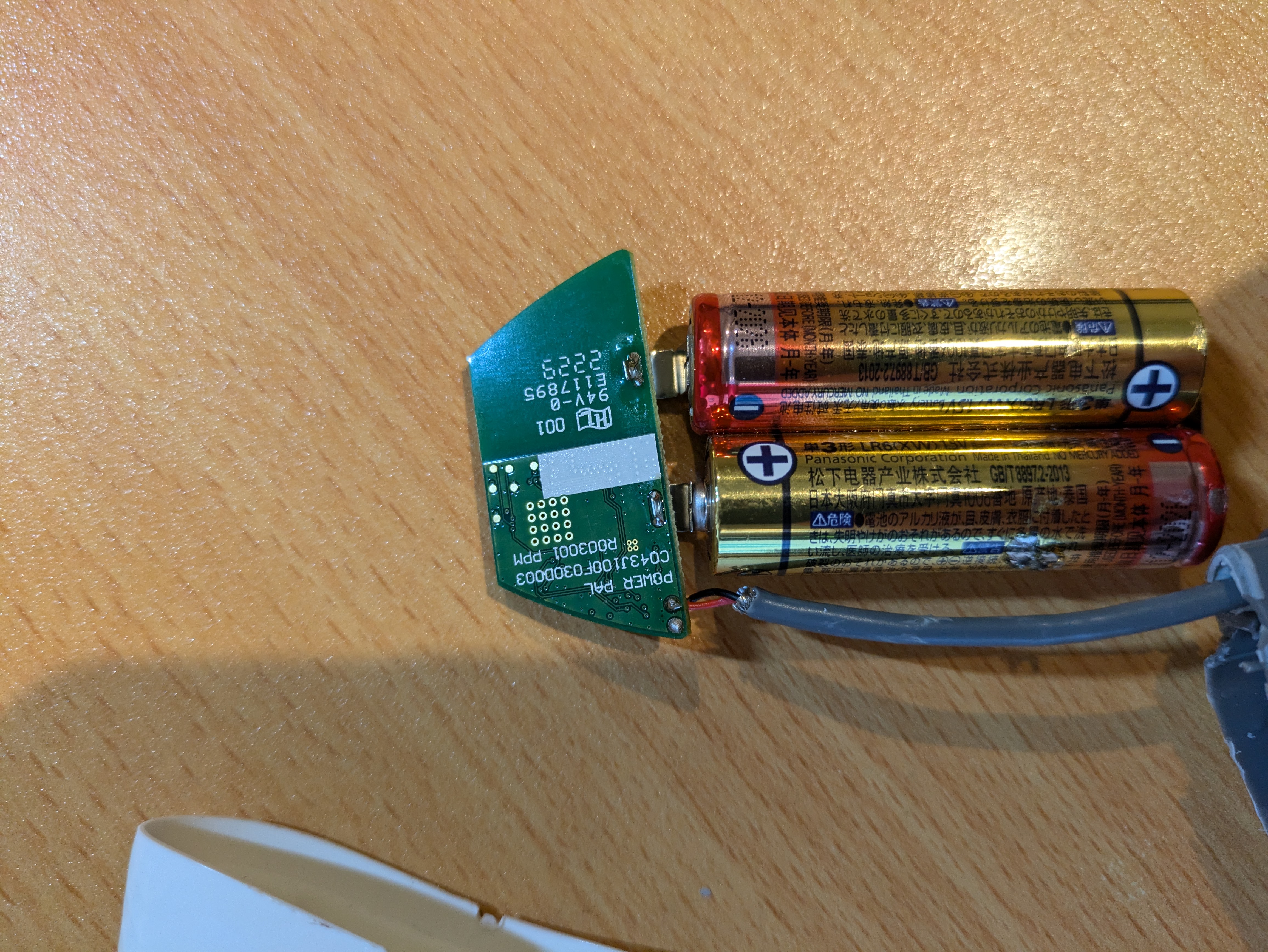
The device is powered by 2 double A batteries that have spot welded metal strips on them, and are glued together. These are easy to replace for someone comfortable with a soldering iron. I question why they didn't make them user replacable. My two guesses: they want you to buy more (they're over $100 each) and/or reduce tech support calls when the units batteries are replaced, as it seems to not have any non-volatile memory for user configurations.
The SOC is a nRF52840 with a 64MHz Cortex M4, 1MB flash and 256KB RAM, BLE and a ton of other peripherals that are not used. This seems very powerful for what it is.
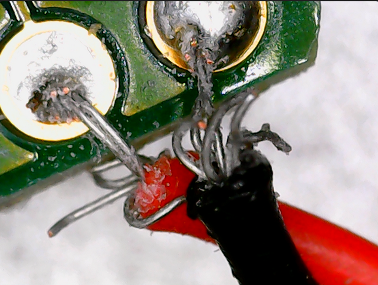
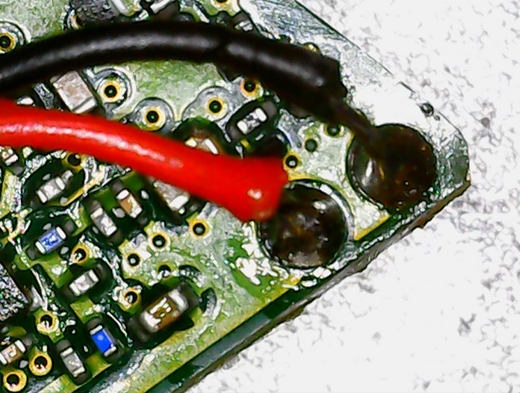
I noticed the soldering of the sensor was very poor from the factory, so I fixed it while I was inside.
I'm integrating this into Home Assistant as the data is free to access from any bluetooth device.


Service monitoring on Googles Cloud Platform
21/08/2024
I had a reason to run an instance of uptime-kuma, which is a service monitor, so I put together a little guide to setting this up on Googles Cloud Platform free tier.
Initial Setup
1. Create Google Cloud account
2. We need to upload a .raw image of Alpine to our Google Cloud account. To do this, create a new bucket at https://console.cloud.google.com/storage/browser
3. Download the Google Cloud Platform build of Alpine at https://alpinelinux.org/cloud/ ensure you select the latest release, x86_64, BIOS, Virtual. Then Download the tiny image
4. GCP requires the image be in .tar.gz format and called disk.raw, so rename the .raw image, then archive it.
5. Upload this .tar.gz to the Google Cloud bucket you made.
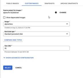
6. We need to create an image that this VM will be based on. Go to https://console.cloud.google.com/compute/images and select Create Image
7. Name your image, select Cloud Storage file as the source, and select the .tar.gz file you uploaded to your bucket. Then click create.
8. Create a new VM instance with the following:
- 1 non-preemptible e2-micro VM instance per month in one of the following US regions:
o Oregon: us-west1 o Iowa: us-central1 o South Carolina: us-east1
- 30 GB-months standard persistent disk
- 1 GB of outbound data transfer from North America to all region destinations (excluding China and Australia) per month

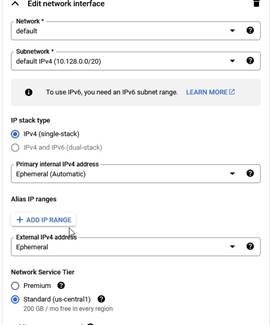
Be sure to select Standard as the Network Service Tier, it is premium by default
Change the Boot disk, under image select the image we made.
Ensure you select Standard persistent disk as the Disk type Set the size to 30GB
Under security, add an ssh public key which will be used to login. At the end of the public key, change the username to alpine.
Virtual Machine
1. Connect to your instance using the ssh key you uploaded and the username alpine: ssh
-i <keyfile> alpine@<ip>
a. You can find your IP in the VM instances tab of GCP
2. Set password, update, install packages
a. echo "alpine:passwordhere" | doas chpasswd
b. doas apk update
c. doas apk upgrade
d. doas apk add docker
e. doas apk add caddy
3. Setup environment
a. doas rc-update add docker default
b. doas rc-update add caddy default
c. printf "<yourdomain.tld>\n{\nreverse_proxy :3001\n}\n" | doas tee -a
/etc/caddy/Caddyfile
d. printf "ChallengeResponseAuthentication no\nPasswordAuthentication no\nPermitRootLogin no\nPermitRootLogin prohibit-password\n" | doas tee
-a /etc/ssh/sshd_config
e. doas reboot
f. reconnect to your vm
4. create and run docker image
a. mkdir /home/alpine/kuma
b. cd /home/alpine/kuma
c. doas docker run -d --dns 1.1.1.1 --restart=always -p 3001:3001 -v /home/alpine/kuma:/app/data --name uptime-kuma louislam/uptimekuma:1-alpine
DDNS
1. The free tier GCP vm has a dynamic IP and I have experienced it changing between reboots. So we need to setup dynamic DNS and a hostname that points to our domain.
a. Add an A record to your DNS records pointing to the vm’s IP
b. Each registrar has their own API for doing DDNS updates, find a script for your service, place it at /home/alpine/scripts/ddns.sh and add it as a cronjob at boot and hourly on your vm
i. chmod +x /home/alpine/scripts/ddns.sh
ii. crontab -e
iii. add: 0 * * * * /home/alpine/scripts/ddns.sh
iv. add: @reboot /home/alpine/scripts/ddns.sh
c. Note, GoDaddy changed their API requirements, unless you have 50 domains with GoDaddy, you may no longer use their DNS API, you’re out of luck.
You can now access uptime-kuma at your domain.