CHIP-8 interpreter #1 - graphics
17/8/2020
I'm working on an implementation of a CHIP-8 interpreter using SDL2 for graphics and sound, in C. I plan to implement the interpreter in parts and have them accompanied with a website post.
What is CHIP-8
CHIP-8 is an interpreted programming language made in the mid 1970's to allow video games to be easier to create and portable for the incompatible systems of the time.CHIP-8 specs:
- 4KB memory
- 16 general purpose 8-bit registers
- 16-bit I register, used to hold memory addresses
- 8-bit delay timer register
- 8-bit sound timer register
- 64x32 display
- 16-bit PC register, stores the current execution address
- 8-bit SP register, points to the top of the stack
- 16-bit stack consisting of 16 values, allowing upto 16 levels of nested subroutines
- 16 key input, hexadecimal 0-F
- default fontset consisting of 0-F in hexadecimal
- 4KB memory
- 0x0 - 0x1FF reserved for the interpreter, in our case this is where we will put the fontset
- 0x200 - 0XFFF program rom and usable program memory
Graphics
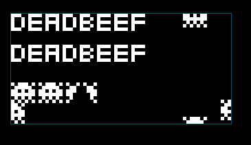
The original CHIP-8 (and the one I'm implementing) uses a 64x32 pixel display. Originally, this would have been viewed on a television of the time, however today we have massive displays - this is just too small. So to fix that we need to implement some scaling, thankfully SDL2 handles this for us.CHIP-8 graphics are drawn using sprites. A sprite is always 8 pixels wide and can be up to 15 pixels tall. Each pixel is a single bit, so each byte has 8 pixels inside it, this equates to a sprite 1 byte wide and up to 15 bytes tall.
As an example, the letter 'E' as a sprite:
| "E" | Binary | Hex |
|
**** * **** * **** |
11110000 10000000 11110000 10000000 11110000 |
0xF0 0x80 0xF0 0x80 0xF0 |
Sprite pixels are not turned off and on as you'd expect, instead they're XOR'd. In my interpreter video memory is an array of 64x32 values. To draw a set pixel of a sprite, the index into video memory is XOR'd with 1 (or in my case 0xFFFFFF). This means if the bit was already turned on, it will be turned off - it's toggling the pixel. In the case of a pixel being turned off because of the XOR, the 0xF register is set to 1 to indicate to the program that a sprite collision has occurred.
If you don't understand the XOR operation see my post detailing how bitwise operations work.
CHIP-8 documentation states that a sprite should wrap around when it is drawn out of bounds. This is achieved with the modulo operator(Modulo is the remained when two numbers are divided, example: 11 modulo 4 = 3, because 11 divides by 4 (twice), with 3 remaining). CHIP-9 has 64x32 display, so imagine the following:
We want to draw a pixel at x coordinate 27. 27 % 32 = 27 - the coordinate stays the same. However, if we try draw a pixel at x coordinate 35 we'll find that 35 % 32 = 3. We've clamped the possible x coordinates to 32, the difference between 35 and 32 is 3, and that is our new X coordinate as it wraps around.
In my interpreter we're treating a 1d array as 2d, so we need to map onto the array (bit is the current bit we're writing, 0-7 for the range of a byte):
destination_in_video_memory = WIDTH*(starty%HEIGHT)+((startx%WIDTH)+bit)
This is the function as it currently stands that draws a sprite to the screen:
void
chip8_draw_sprite(int startx, int starty, uint16_t mem, uint8_t size)
{
	/*
	 * draw sprite located at loc of height size at startx,starty
	 */

	uint8_t byte = 0;
	uint8_t mask = 0x1;
	V[0xF] = 0; /* set collision register to 0 */
	for (uint8_t byteoffset = 0; byteoffset < size; byteoffset++)
	{
		/* loop through each byte from mem to mem+size */
		byte = memory[mem+byteoffset];
		int bit = 0;
		for (mask = 0x80; mask != 0; mask >>= 1)
		{
			if (byte & mask)
			{
				uint32_t pixel = WIDTH*(starty%HEIGHT)+((startx%WIDTH)+bit);
				if (video[pixel] != 0)
				{
					/* if the video bit is already set, we need to set the collision register */
					V[0xF] = 1;
				}
				video[pixel] ^= 0xFFFFFF;
			}
			bit++;
		}
		starty++;
	}
}
This is written only for testing purposes, when I get to implementing the CHIP-8 instructions it will be rewritten.The general gist of the function is:
- set the collision register (0xF) to 0
- loop through size bytes in memory starting at the offset mem
- loop through each bit of each byte
- perform our modulo operations to perform screen wrapping
- if the pixel at our selected video memory location is already set, set the collision register to 1
- XOR the selected pixel in video memory with 1 (in my case 0xFFFFFF) to flip its value

More posts should follow eventually detailing the other components.
The source code can be found in my git repository.
page generated 8/6/2025 using websitegenerator in C


