


Program/script launching keypad
1/08/2022
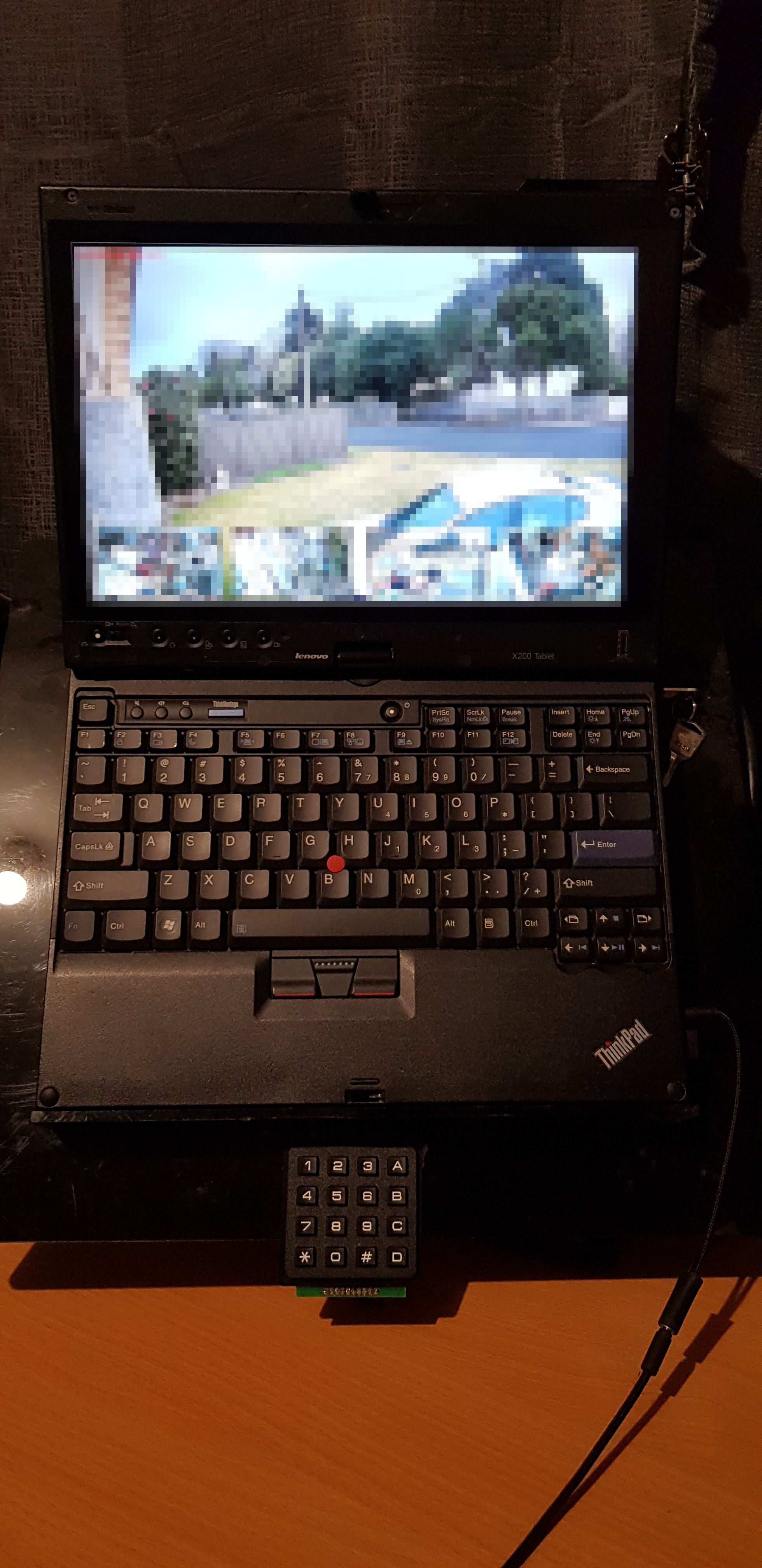
I have various cameras around inside/outside my house. Originally to view them I was displaying them on a 10 second rotation, however this gave me no control and often i'd find myself looking at something happening on a camera only for it to switch.
I have a keypad and arduino laying around so I thought it'd be neat to add in controls.
I have 5 cameras in this view (I have more inside my house in areas I don't want to always look at), so the keypad buttons 1-A will swap whichever camera is "minimised" to the main view. I use motion to manage and record my cameras, the minimised cameras are substreams, so use less bandwidth than the main view. Each camera is also capable of IR mode and switch when it gets dark. I also have IR floodlights on the outside of the house for bright night viewing (the cameras have IR LEDs as well, however outside it is nice to have more).
To listen via serial and actually execute programs/scripts, I wrote a C program. It connects over serial, receives the key pressed and takes action according to what is assigned to each key. The assignments are controlled via a .ini file, the key value can either be the word "cam" which means a camera command, or a program name/script that is to be executed. The program then forks off and exectutes whatever you desire. Camera commands are different - I use wServer as a very simple websocket server that accepts connections from a websocket client (the viewer), the server then sends the client whatever key I press if it is assigned as a camera command.
To view/control the cameras and receive commands I use a basic html/javascript pairing.
I also recently made a laptop vesa mount tray which I have my laptop sitting on now to save desk space. Commercial laptop tray offerings were all too thin to support my girthy x200 and ultrabase. Also I'm using my x200 tablet temporarily while I figure out issues with my plain x200's.


Serial console via rpi zero
14/6/2022
The other day I was doing some networking changes on a server upstairs. Without thinking of the consequences I took the ethernet interface down with the intention of bringing it back up - however I was connected via ssh on that interface so I lost connection. I had to do a shameful walk upstairs to recover.
I have a spare rpi zero and a USB to rs232 cable and thought it'd be neat to get a recovery console using these (accessible over ssh to the pi). However I wasn't sure about the voltages and if i'd need extra hardware to deal with this, but while researching I found it can be done via the data USB port, called "USB Gadget Serial".
Setting this up was easy - connect the rpi zero to the server via USB (I also am powering the pi from a UPS), have it run an ssh server and do some simple config changes:
- on the pi add dtoverlay=dwc2 to /boot/config.txt
- on the pi add modprobe g_serial above exit 0 in /etc/rc.local
- on the server enable getty on ttyACM0 systemctl enable --now serial-getty@ttyACM0.service
Now you can open a connection to the server using screen /dev/ttyGS0, even when the networking is broken.


IBM Model M restoration
17/2/2022
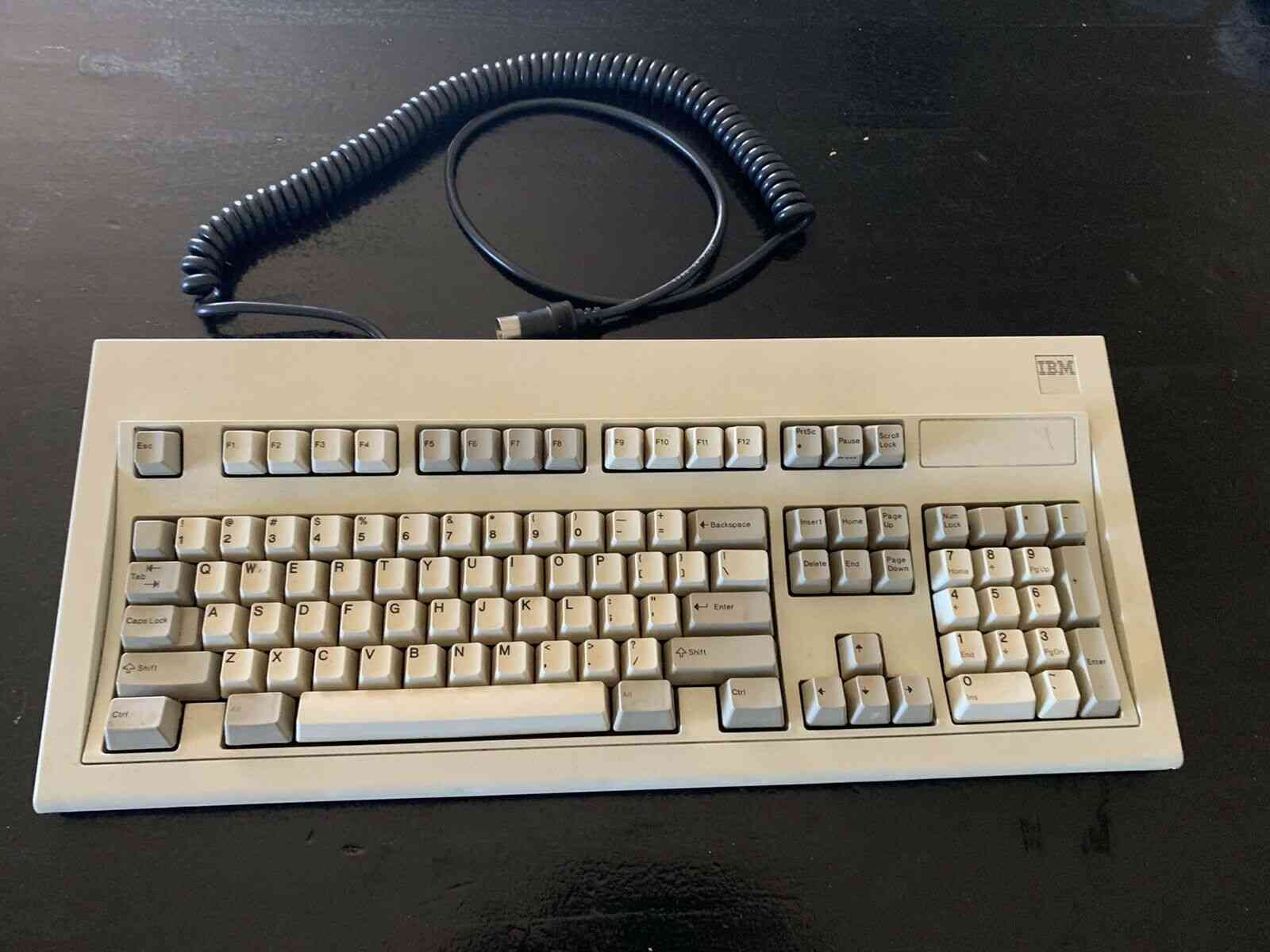
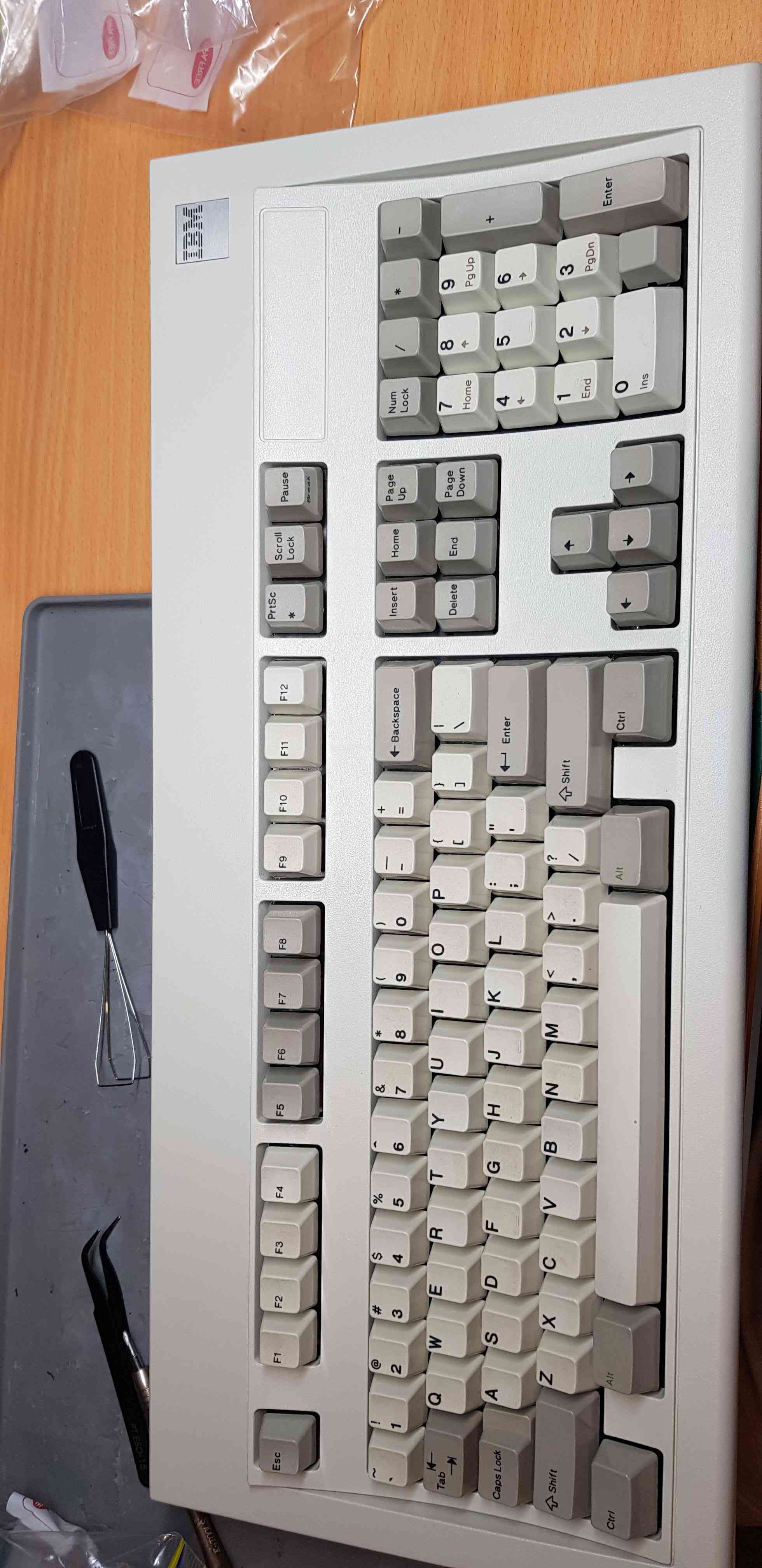
I first purchased an IBM Model M a few months ago, recently I bought another one from ebay. The condition seemed ok visually - some missing key caps and a scratch or two. It is a 1390120 from 1986:
However when I got it, the keyboard felt like typing on a sponge, it obviously needed to have a bolt modification performed on it. This modification involves dismantling the keyboard and replacing plastic rivets holding the membrane together with bolts.
to perform this modification you need a few tools and bolts. Places on the internet will claim you need ~80 M2 2mm machine screws/bolts and ~80 matching M2 nuts and matching washers. This isn't true. I used maybe 20 bolts and nuts, and no washers (even though I ordered them), there just isn't room to put them on.
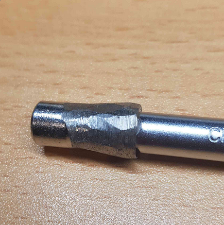
Another tool you will need is a 5.5mm driver. This is quite a unique driver size, however I happened to have one. Unfortunately though it was too fat to fit into the recessed holes the case bolts are fitted into. So I ended up grinding my 5.5mm driver bit down on a bench grinder.
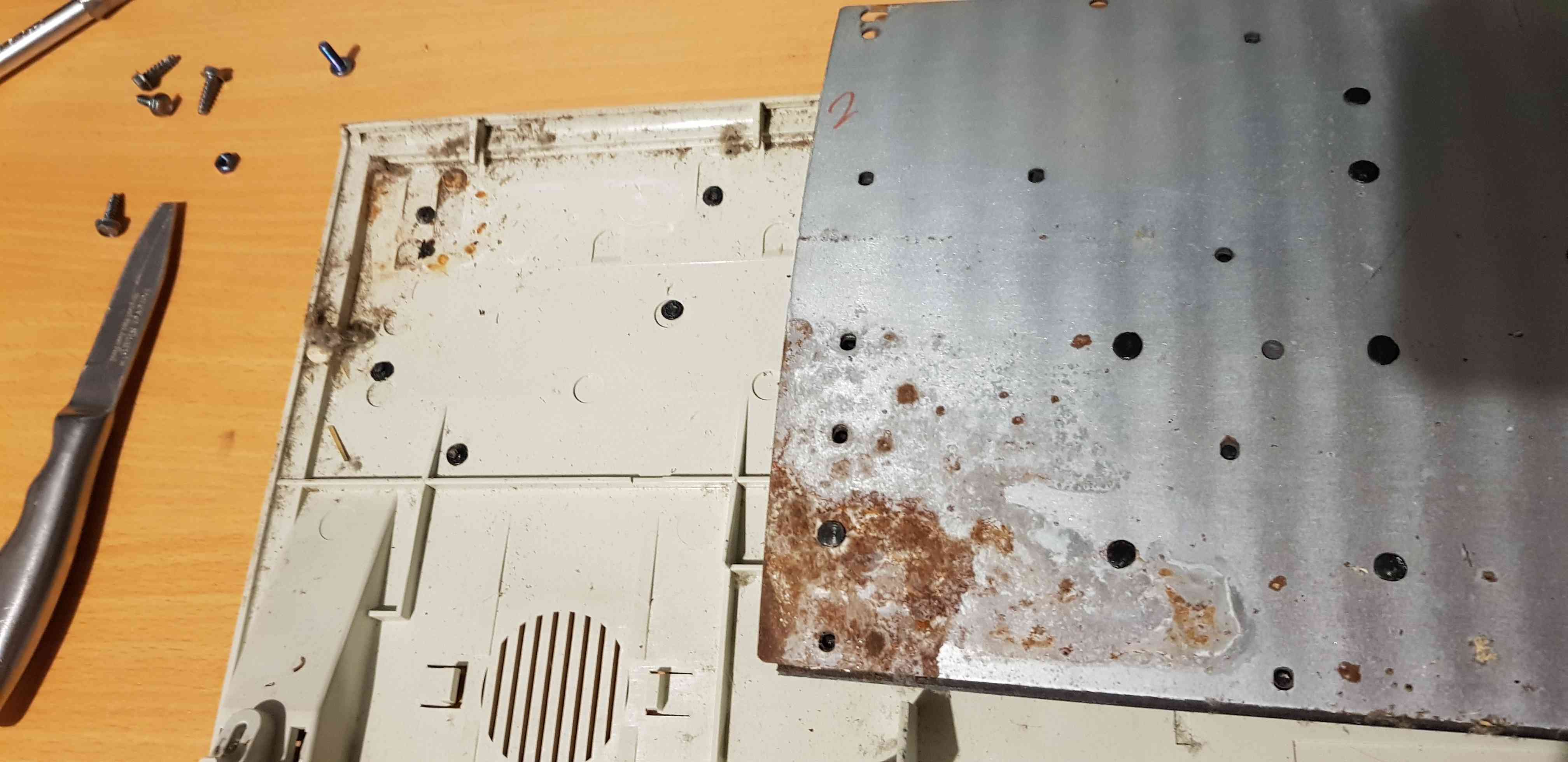
With the case removed, the damage and dirt can be inspected:
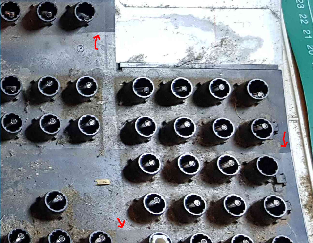
It took me awhile to notice (and for it to snap in half) for me to notice the barrel plate had cracks, and was prone to snapping. (see the arrows) These cracks extend along the whole length of the plate:
I found epoxy resin to be incredibly good for fixing this problem, you can see i glued it back together and filled in the crack on both sides:
I proceeded to clean all the keys, caps, plate, case, sand away the rust etc - that isn't interesting.
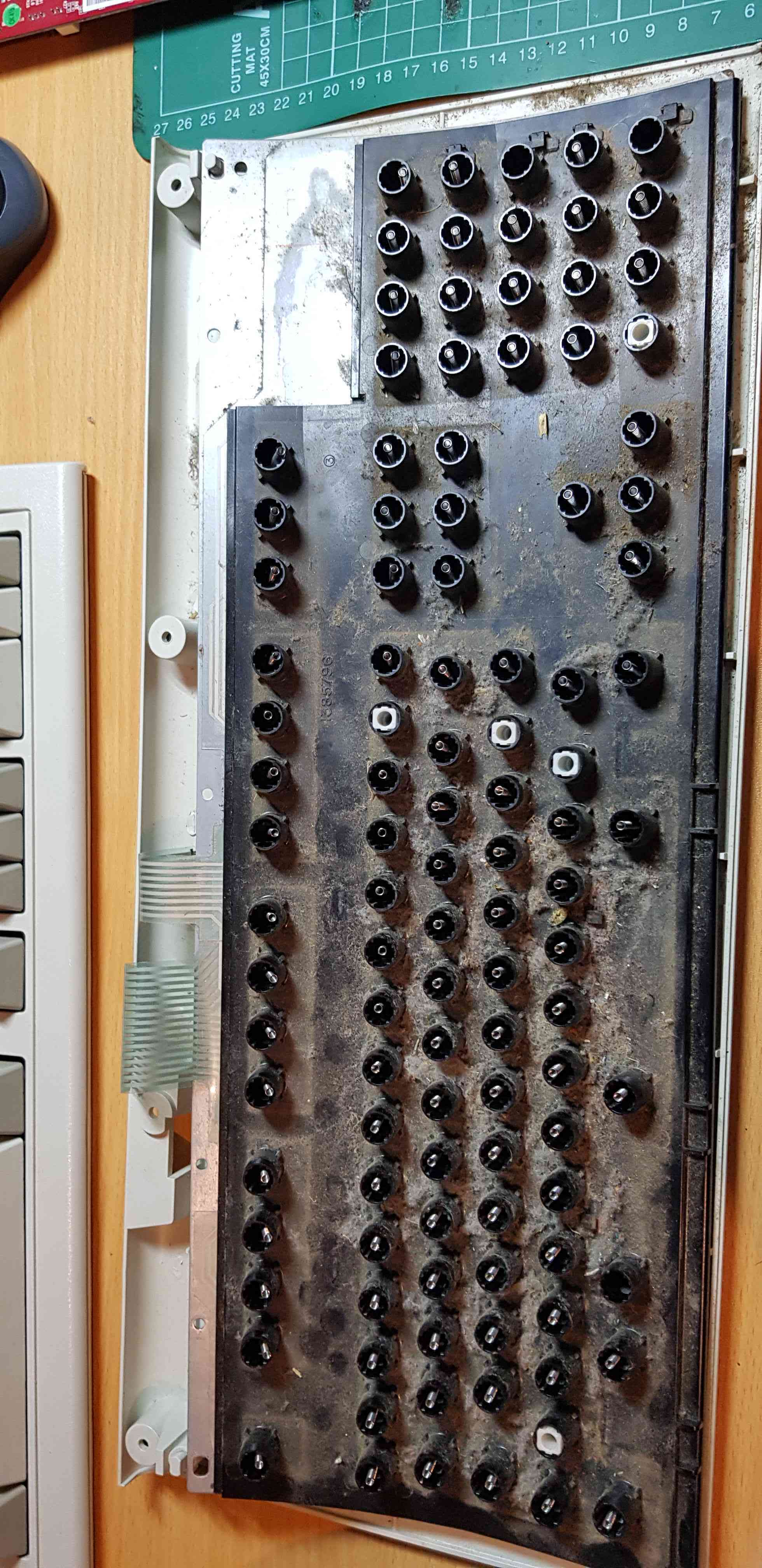
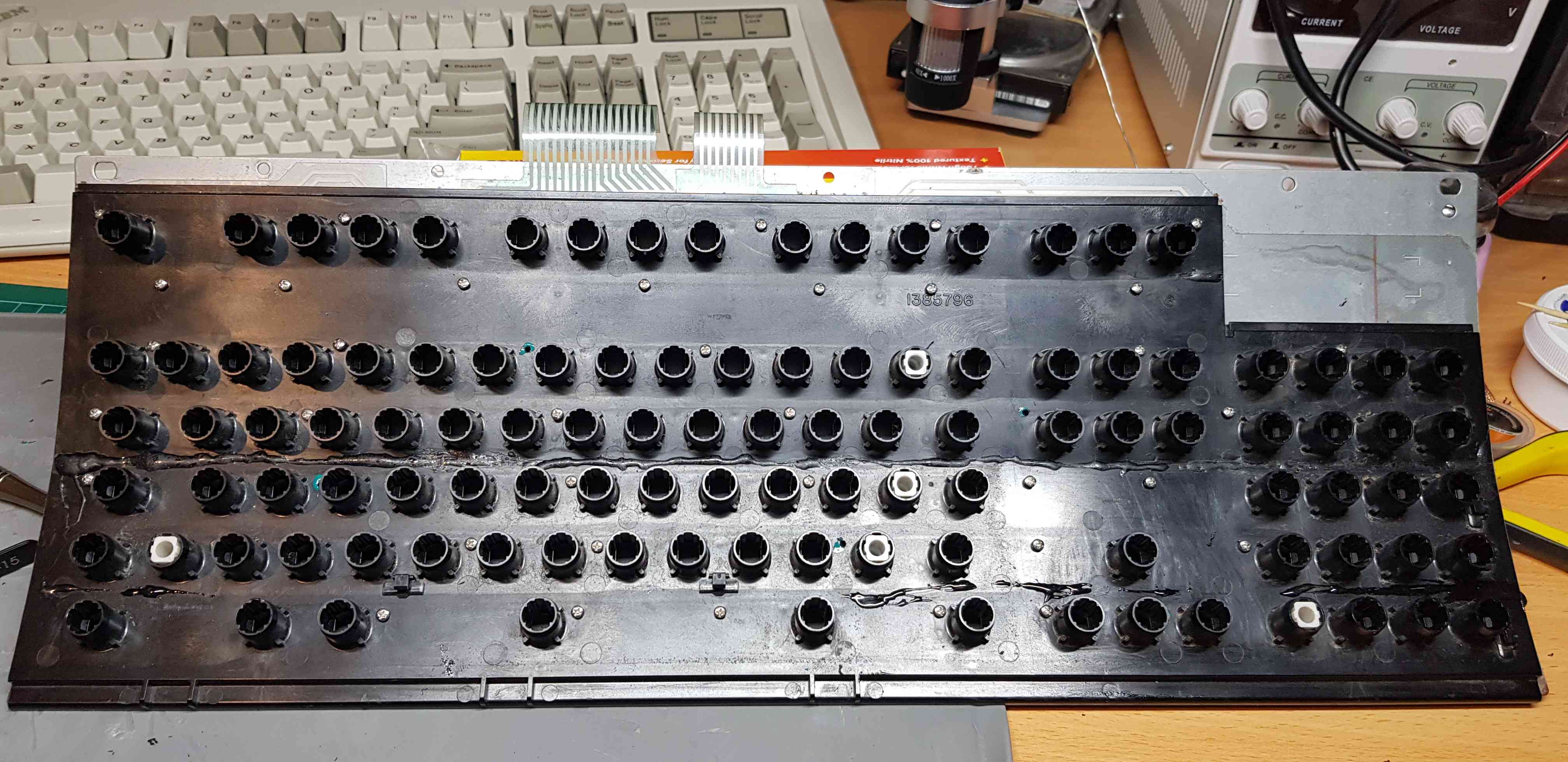
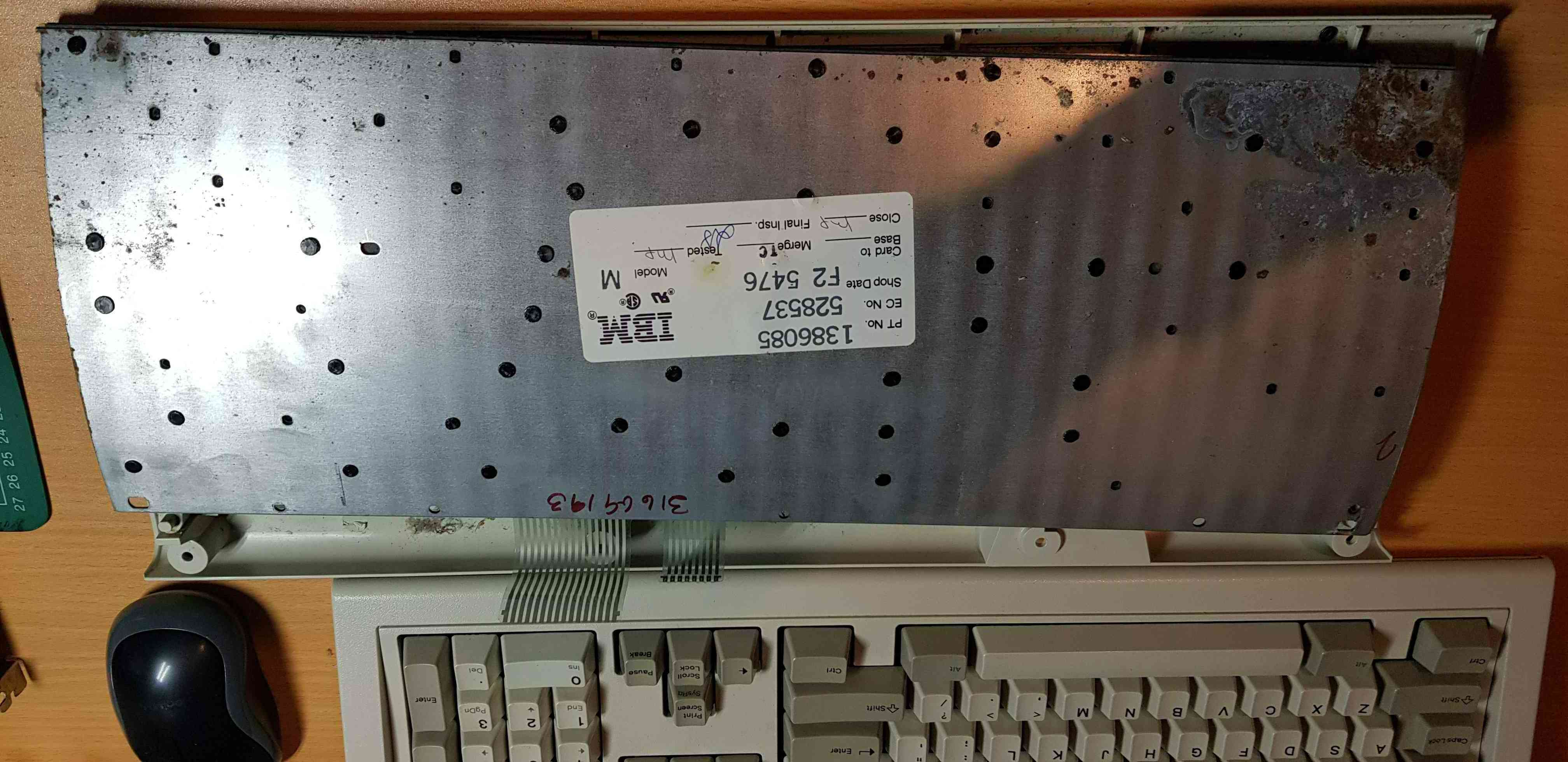
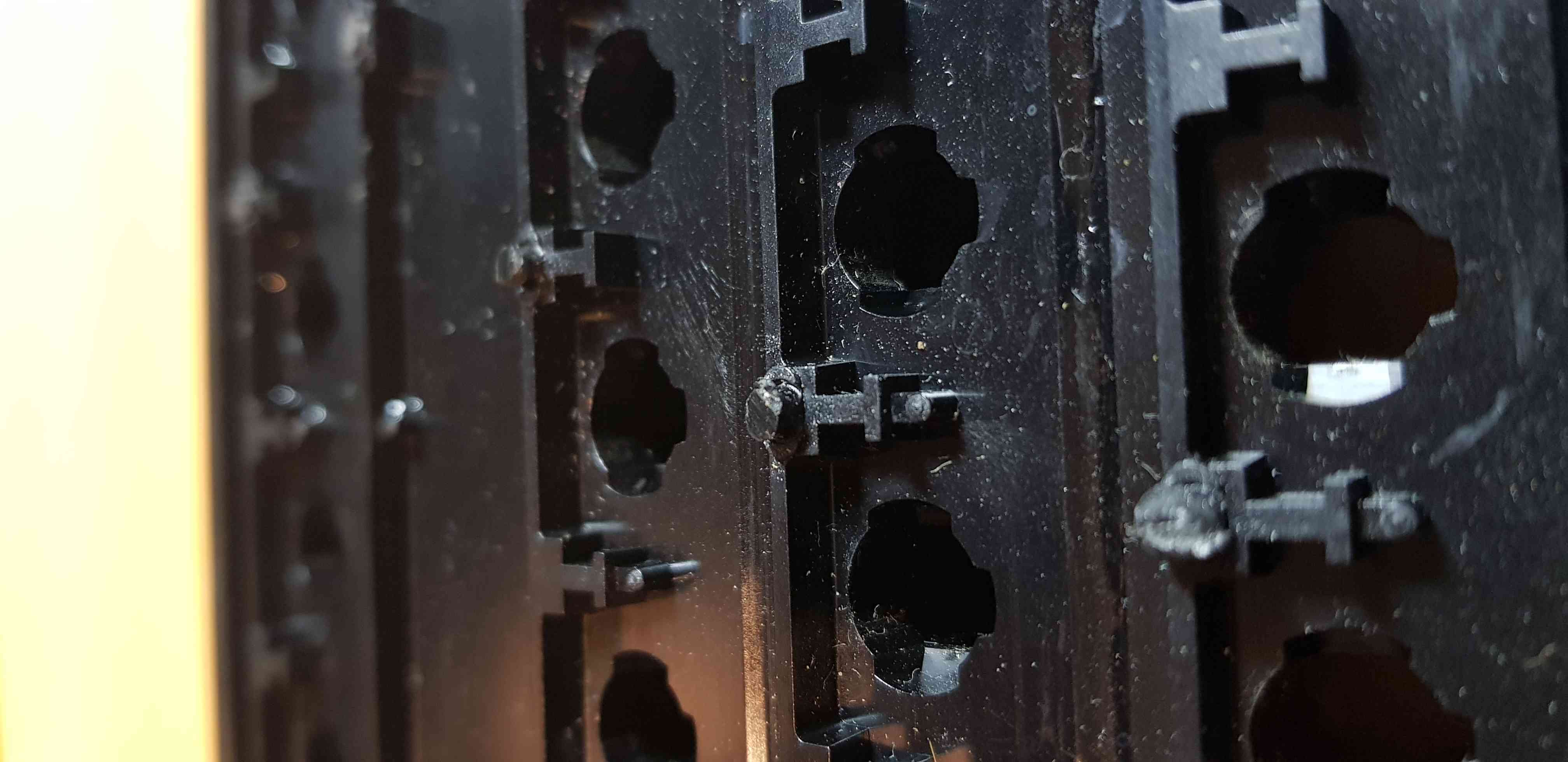
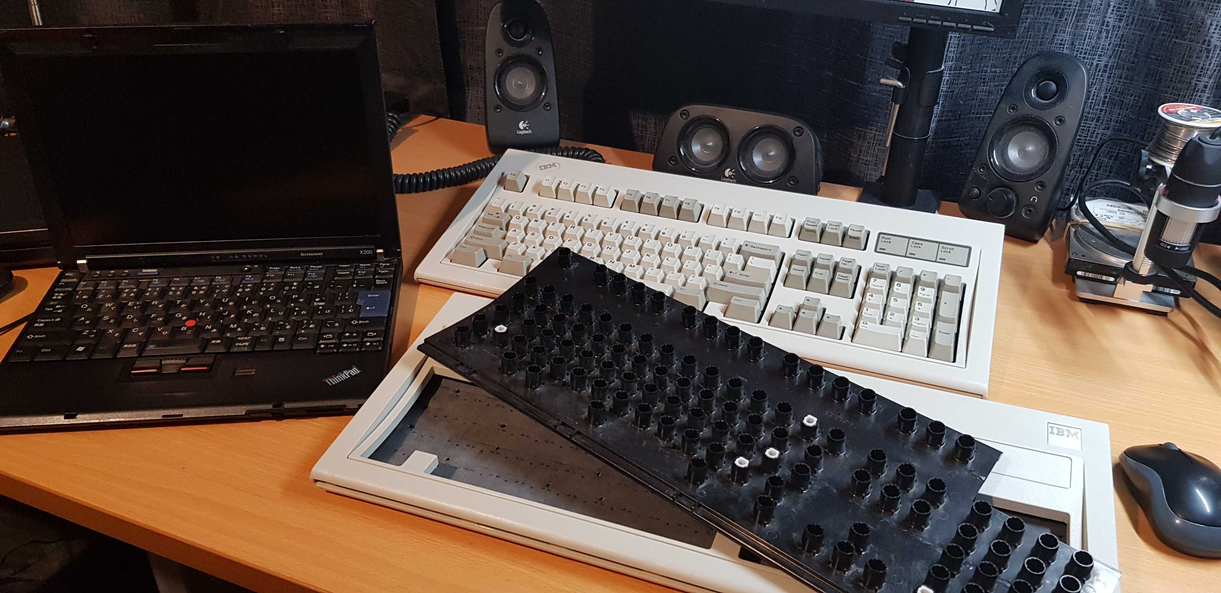
Pictured below the back of the metal plate that holds the key membrane sandwich. The Model M has a major design flaw in that the rivets (the black circles below) used to hold this sandwich together is made of plastic that over time degrades and breaks. It only takes a handful of these to break for the membrane to no longer be held together tight enough for keys to register and feel correct, this is why we replace them with bolts. Mine doesn't look that bad, but it felt bad and did not register keys properly.
I cut off the rest of the rivets using a small craft knife. This let the membrane sandwich come apart into 3 pieces: the barrel plate, a cloth protector and the back metal plate. My model M seems unique as only a few others online have their membrane physically glued to the backplate. It is usually 5 pieces. The posts that were left over by the rivets needed to be cut flat, I did that using nail clippers.
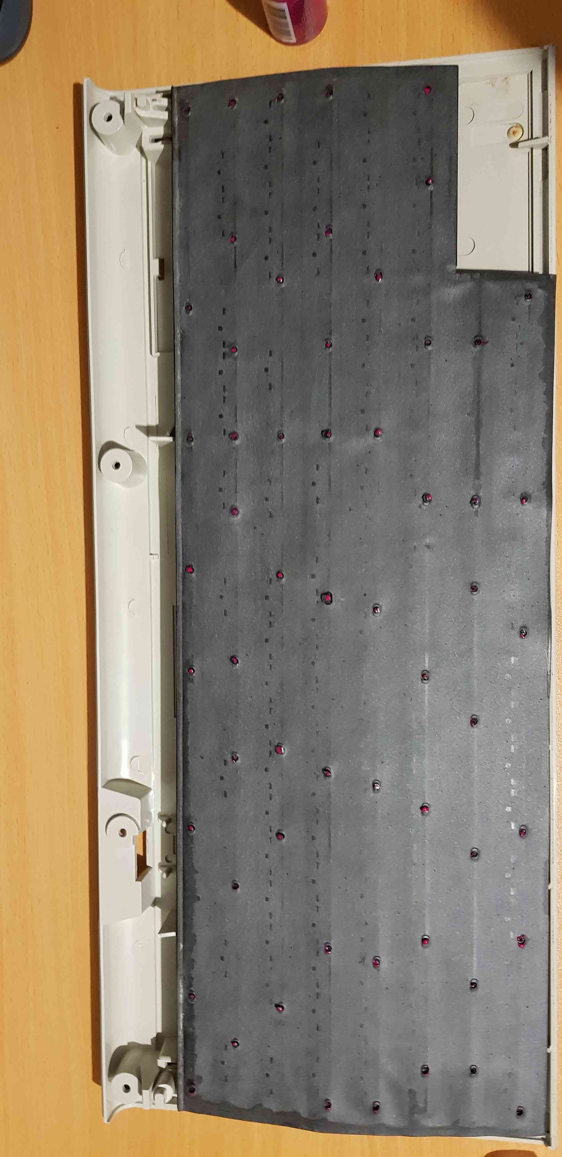
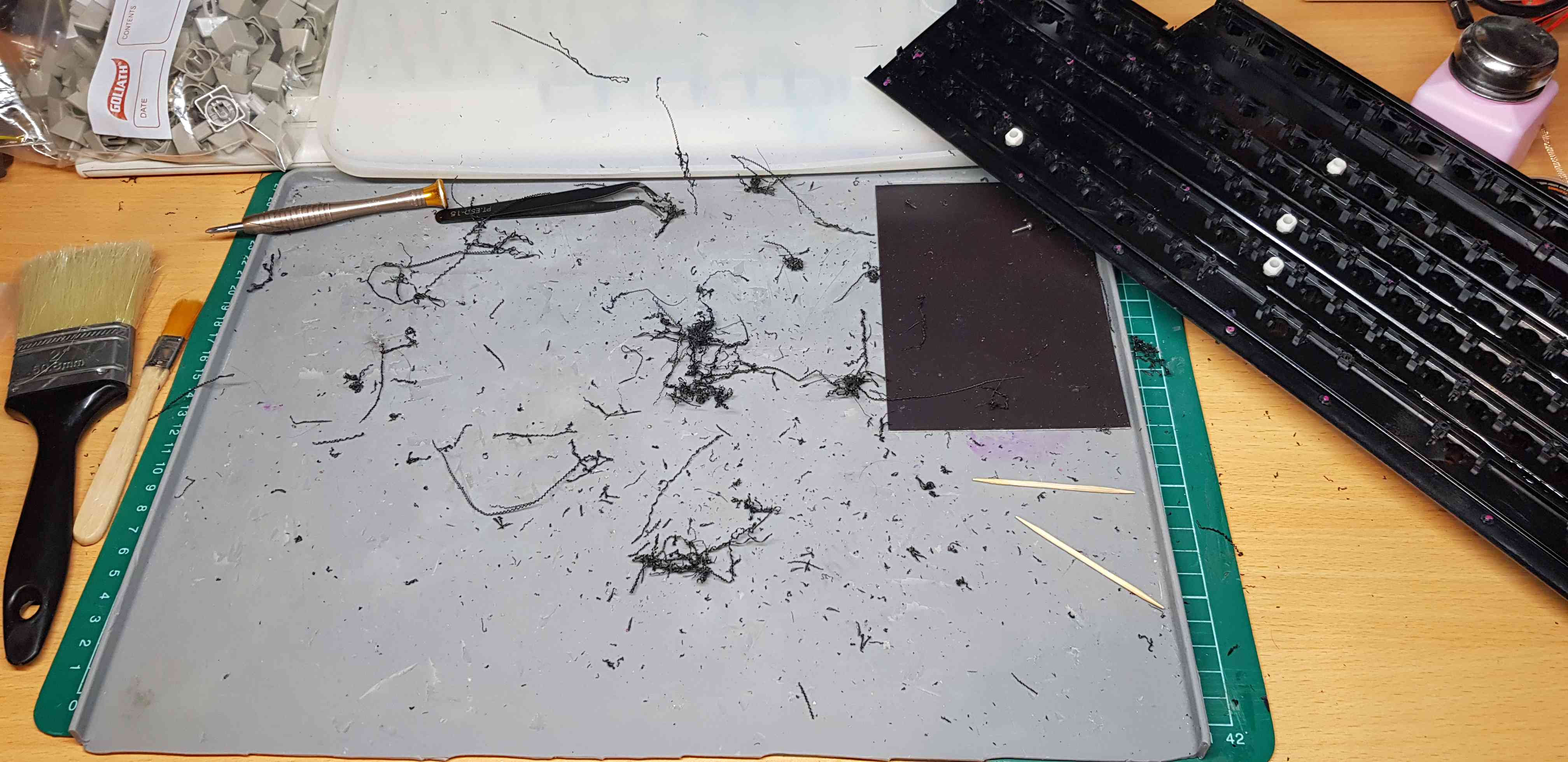
The next step is to drill holes through the barrel plate where the old rivets were located. To do this you use a 1/16" drill bit. To help with the drilling I first marked each post I would have to drill through using some nail polish:
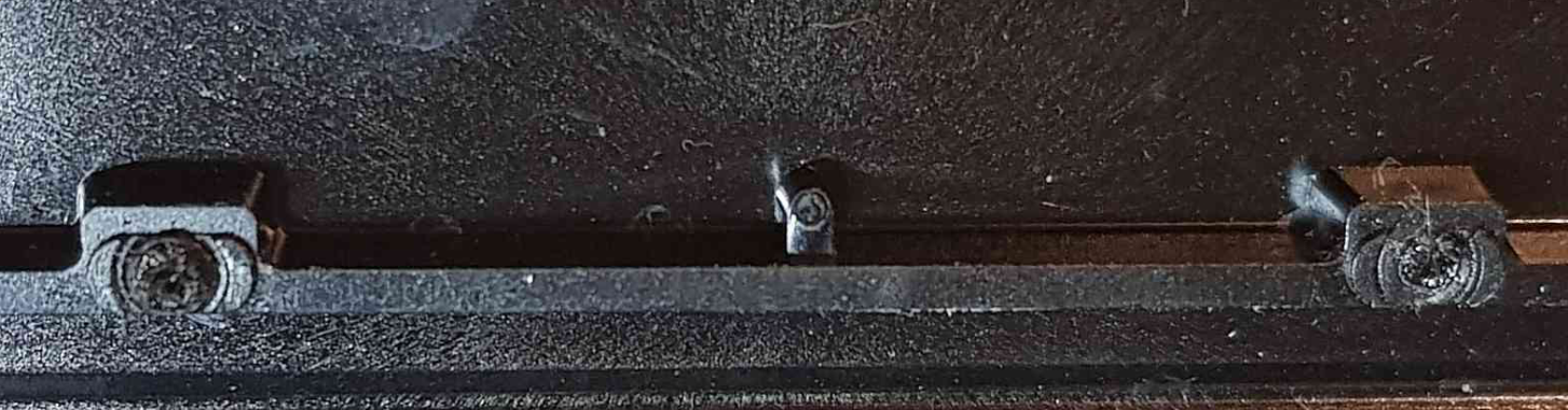
Then, using a soldering iron I don't mind destroying the tip on, I slightly melted through the top of the posts as a guide for the drill bit:
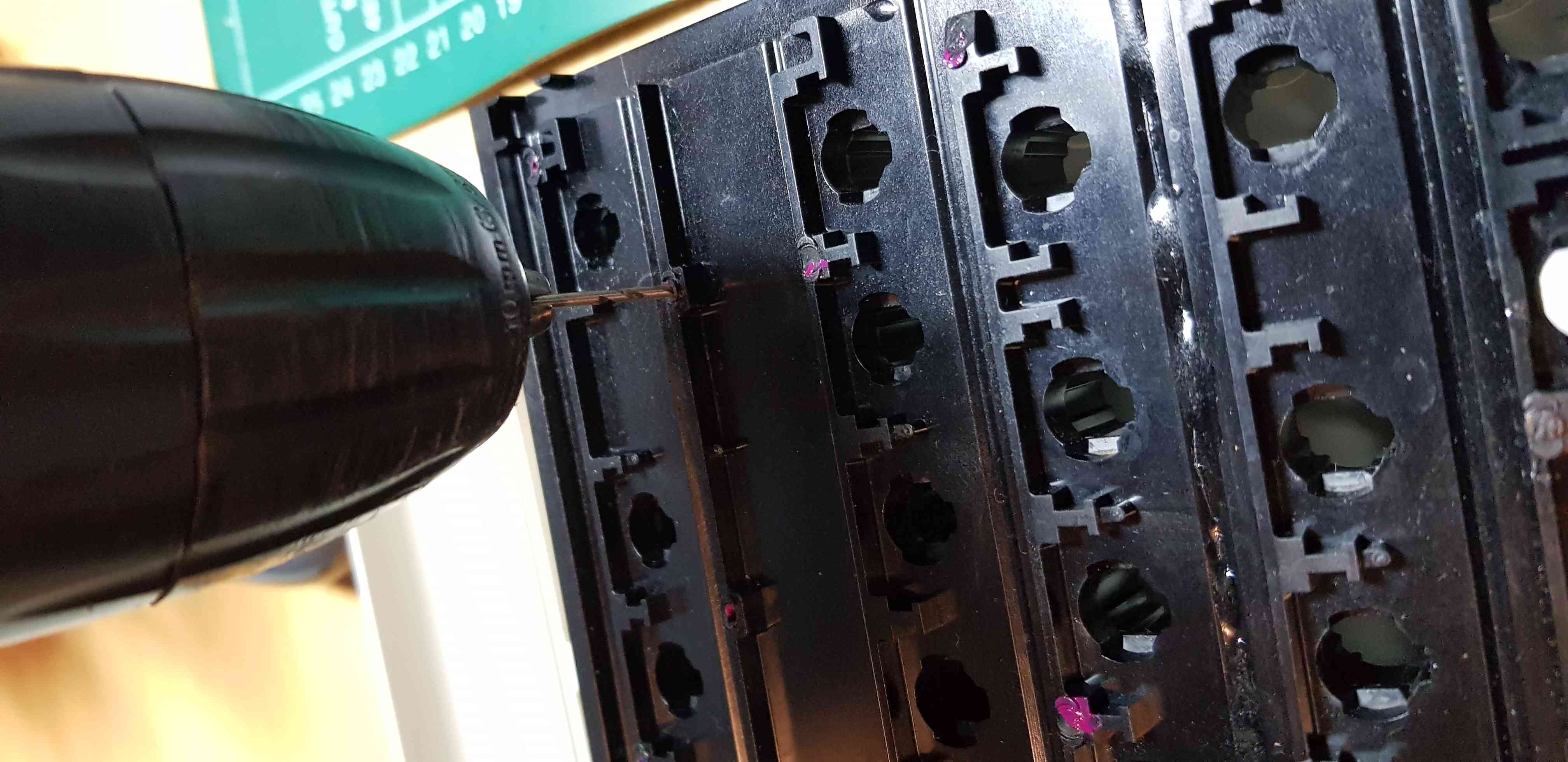
Now I started drilling. This was scary because I thought accuracy was important. It is not, I was sloppy and inaccurate but only a couple holes didn't line up in the end, and like I said, you do not need all rivets replaced. It also makes a mess:
I then reassembled the membrane sandwich, installed the screws and nuts, put it all back together and I had a finished Model M.


Userspace driver for Microsoft serial mouse
9/1/2022
To learn the basics of serial programming in UNIX I created a simple userspace driver for a Micrsoft serial mouse.
I use uinput to emulate an input device.
/*
 * Microsoft mouse
 */

#include <stdio.h>
#include <stdlib.h>
#include <string.h>
#include <unistd.h>
#include <fcntl.h>
#include <errno.h>
#include <termios.h>
#include <ctype.h>
#include <stdint.h>
#include <linux/uinput.h>

#define DOWN 		1
#define UP 		0

#define PORT 		"/dev/ttyUSB0"
#define BAUD 		B1200
#define LBIT 		1 << 5
#define RBIT		1 << 4
#define SYNCBIT 	1 << 7
#define XBYTE0MASK	0x03
#define XBYTE1MASK 	0x7F
#define YBYTE0MASK	0x0C
#define YBYTE2MASK 	0x7F

void process(void);
void emit(int fd, int type, int code, int val);

uint8_t packet[3];

struct
{
	uint8_t left;
	uint8_t right;
} mouse;

struct uinput_setup usetup;
int ud;

int
main(void)
{
	int fd, flags, onbyte;
	ssize_t byte;
	struct termios options;
	fd = open(PORT, O_RDWR | O_NOCTTY);
	if (fd == -1)
	{
		perror("cannot open serial device");
		exit(EXIT_FAILURE);
	}
	flags = fcntl(fd, F_GETFL);			// get current flags
	fcntl(fd, F_SETFL, flags & ~O_NONBLOCK);	// mask out O_NONBLOCK = blocking

	// get port options and set flags
	tcgetattr(fd, &options);
	cfsetispeed(&options, BAUD);
	cfsetospeed(&options, BAUD);
	options.c_cflag |= (CLOCAL | CREAD);	// local line, enable read
	// set character size
	options.c_cflag &= ~CSIZE;		// mask out the character size bits
	options.c_cflag |= CS7;			// 7 bits
	// no parity
	options.c_cflag &= ~PARENB;		// mask out parity bit
	options.c_cflag &= ~CSTOPB;		// mask out stop bit (unset = 1 bit)
	// raw input
	options.c_lflag &= ~(ICANON | ECHO | ECHOE | ISIG);
	options.c_iflag &= ~INPCK; 		// mask out parity checking
	options.c_oflag &= ~OPOST;		// mask out postprocessing - raw output

	options.c_cc[VMIN] = 1;			// minimum of 1 byte read
	options.c_cc[VTIME] = 0;		// wait indefinitely
	// apply options
	tcsetattr(fd, TCSANOW, &options);

	// setup uevent device

	ud = open("/dev/uinput", O_WRONLY | O_NONBLOCK);
	if (ud == -1)
	{
		perror("cannot open /dev/uinput");
		exit(EXIT_FAILURE);
	}


	// enable mouse left/right and relative events
	ioctl(ud, UI_SET_EVBIT, EV_KEY);
	ioctl(ud, UI_SET_KEYBIT, BTN_LEFT);
	ioctl(ud, UI_SET_KEYBIT, BTN_RIGHT);

	ioctl(ud, UI_SET_EVBIT, EV_REL);
	ioctl(ud, UI_SET_RELBIT, REL_X);
	ioctl(ud, UI_SET_RELBIT, REL_Y);

	memset(&usetup, 0, sizeof(usetup));
	usetup.id.bustype = BUS_USB;
	usetup.id.vendor = 0x1234;
	usetup.id.product = 0x5678;
	strcpy(usetup.name, "Userspace Microsoft serial mouse");

	ioctl(ud, UI_DEV_SETUP, &usetup);
	ioctl(ud, UI_DEV_CREATE);

	mouse.left = 0x00;
	mouse.right = 0x00;
	onbyte = 0;
	byte = 0x00;

	while(1)
	{
		read(fd, &byte, 1);
		if (byte == 0xcd) 		// some kind of init?
			continue;
		// is byte first of packet?
		if (byte & SYNCBIT && onbyte == 0)
		{
			packet[0] = byte;
			onbyte = 1;
		}
		else if (onbyte == 1)
		{
			packet[1] = byte;
			onbyte = 2;
		}
		else if (onbyte == 2)
		{
			packet[2] = byte;
			onbyte = 0;
			process();
		}
		fflush(stdout);
	}
	close(fd);
	ioctl(ud, UI_DEV_DESTROY);
	close(ud);
	return 1;
}

void
process(void)
{
	int8_t relx, rely;
	printf("0x%02x\t", packet[0]);
	printf("0x%02x\t", packet[1]);
	printf("0x%02x\t\n\n", packet[2]);
	if (packet[0] & LBIT && !mouse.left)
	{
		mouse.left = DOWN;
		puts("left down");
		emit(ud, EV_KEY, BTN_LEFT, 1);
		emit(ud, EV_SYN, SYN_REPORT, 0);
	}
	else if (mouse.left && !(packet[0] & LBIT))
	{
		mouse.left = UP;
		puts("left up");
		emit(ud, EV_KEY, BTN_LEFT, 0);
		emit(ud, EV_SYN, SYN_REPORT, 0);
	}
	if (packet[0] & RBIT && !mouse.right)
	{
		mouse.right = DOWN;
		puts("right down");
		emit(ud, EV_KEY, BTN_RIGHT, 1);
		emit(ud, EV_SYN, SYN_REPORT, 0);
	}
	else if (mouse.right && !(packet[0] & RBIT))
	{
		mouse.right = UP;
		emit(ud, EV_KEY, BTN_RIGHT, 0);
		emit(ud, EV_SYN, SYN_REPORT, 0);
	}

	relx |= ((packet[0] & XBYTE0MASK)<<6) | (packet[1] & XBYTE1MASK);
	rely |= ((packet[0] & YBYTE0MASK)<<4) | (packet[2] & YBYTE2MASK);
	emit(ud, EV_REL, REL_X, relx);
	emit(ud, EV_REL, REL_Y, rely);
	emit(ud, EV_SYN, SYN_REPORT, 0);


}

void
emit(int fd, int type, int code, int val)
{
	struct input_event ie;
	ie.type = type;
	ie.code = code;
	ie.value = val;
	/* timestamp values below are ignored */
	ie.time.tv_sec = 0;
	ie.time.tv_usec = 0;

	write(fd, &ie, sizeof(ie));
}


Various updates
1/1/2022
I haven't made a post in over 6 months because my website generator has had a bug with pagination and I haven't bothered to do anything about it.
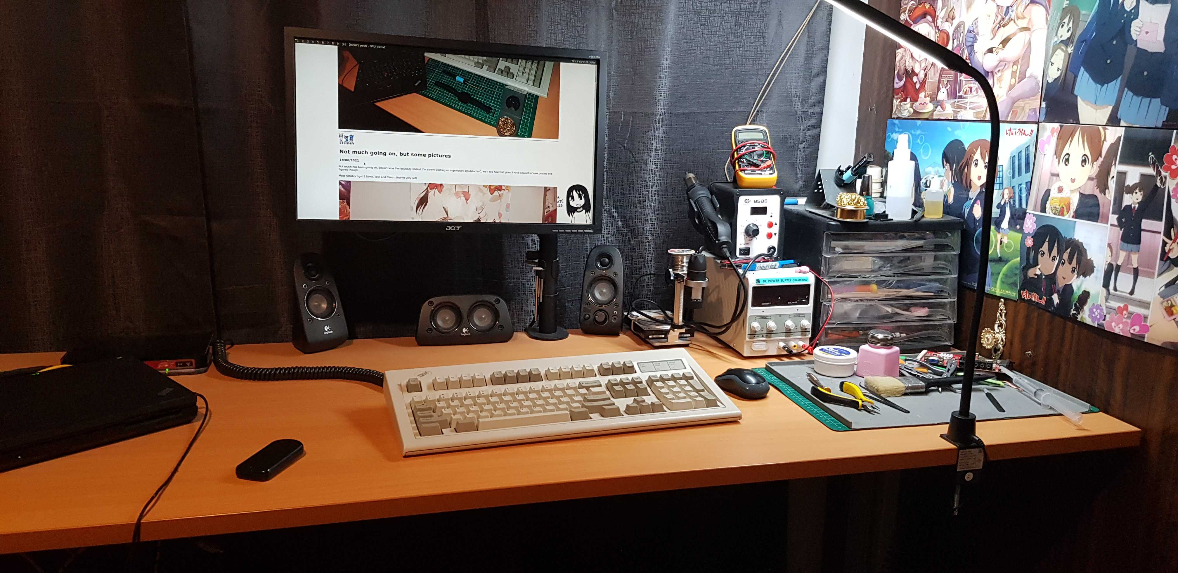
I've become very interested in the hobby of soldering and have spent a lot of time practicing. I acquired a Pinecil iron, a holder, hotair station, DC power supply, cheap microscope, extra ts100 soldering tips, flux/solder/alcohol dispenser/good precision tweezers etc. I've been taking things apart, removing components and soldering them back on, mostly laptop motherboards. I've repaired a few broken items of mine so far (a wire breaking in a servo motor, ch341a voltage mod, a "smart" light bulb for a family member with an internal trace ripped), so these skills have come into use.
I purchased another Thinkpad x200, this time a Japanese import with a JIS keyboard, I think it's pretty neat.
I purchased two IBM Model M keyboards from ebay (1391401 from 1988 and a 1390120 from 1986). One keyboard was in great mechanical and electrical condition, I just disassembled the shell and cleaned each key and the shell, it works perfectly and I am using it now. The other, the 1390120 with a square medal badge from 1986 felt like typing on a sponge. So I have completely cleaned the shell/keys and am waiting on hardware to arrive to bolt mod it.
I'm going to start putting out more posts.
Here is a couple of photos of my soldering/desk setup and the x200 and keyboards.


Not much going on, but some pictures
18/06/2021
Not much has been going on, project wise I've basically stalled. I'm slowly working on a gameboy emulator in C, we'll see how that goes. I have a bunch of new posters and figures though.
Most notably I got 2 fumo, Tewi and Cirno - they're very soft.


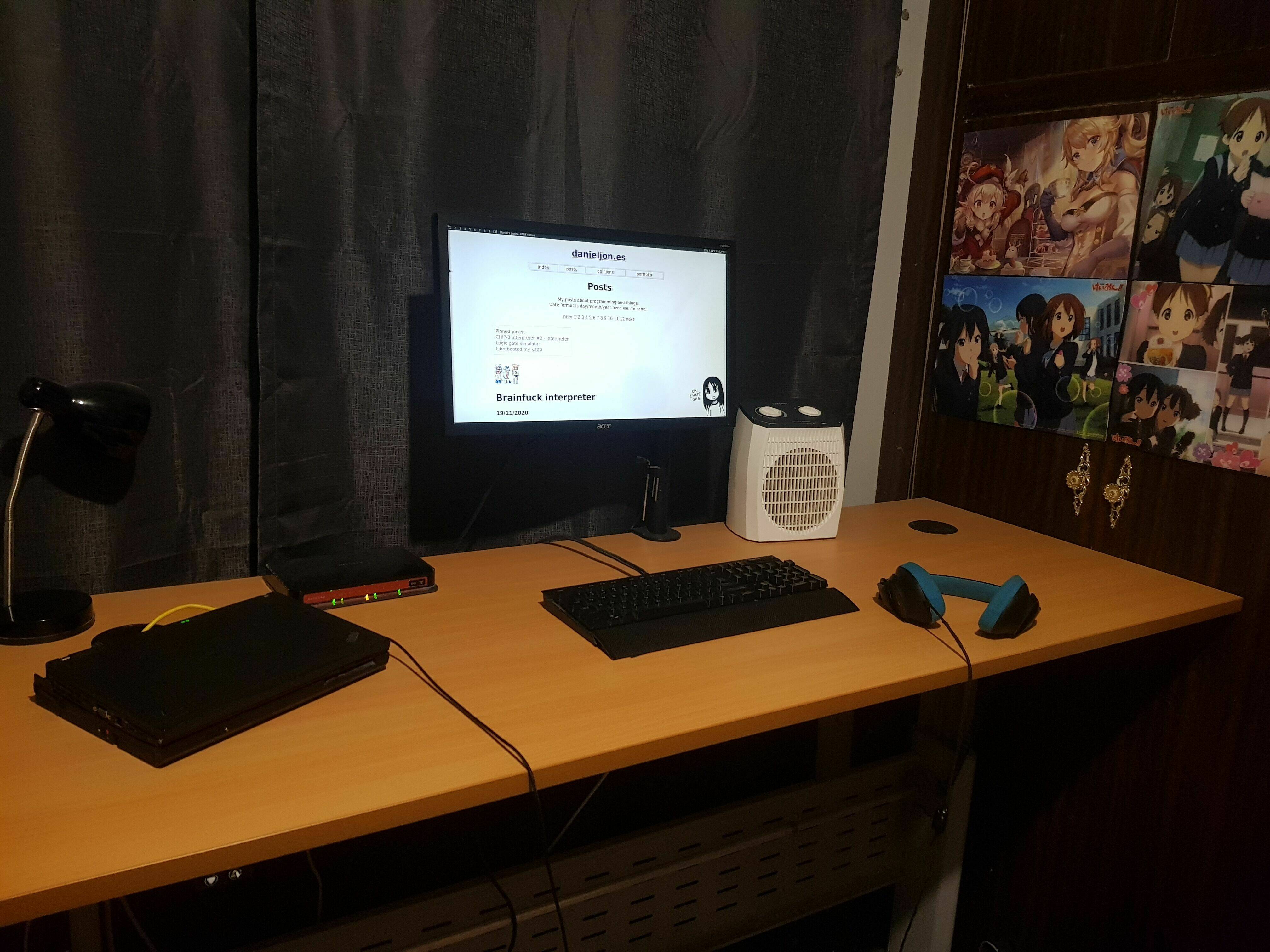
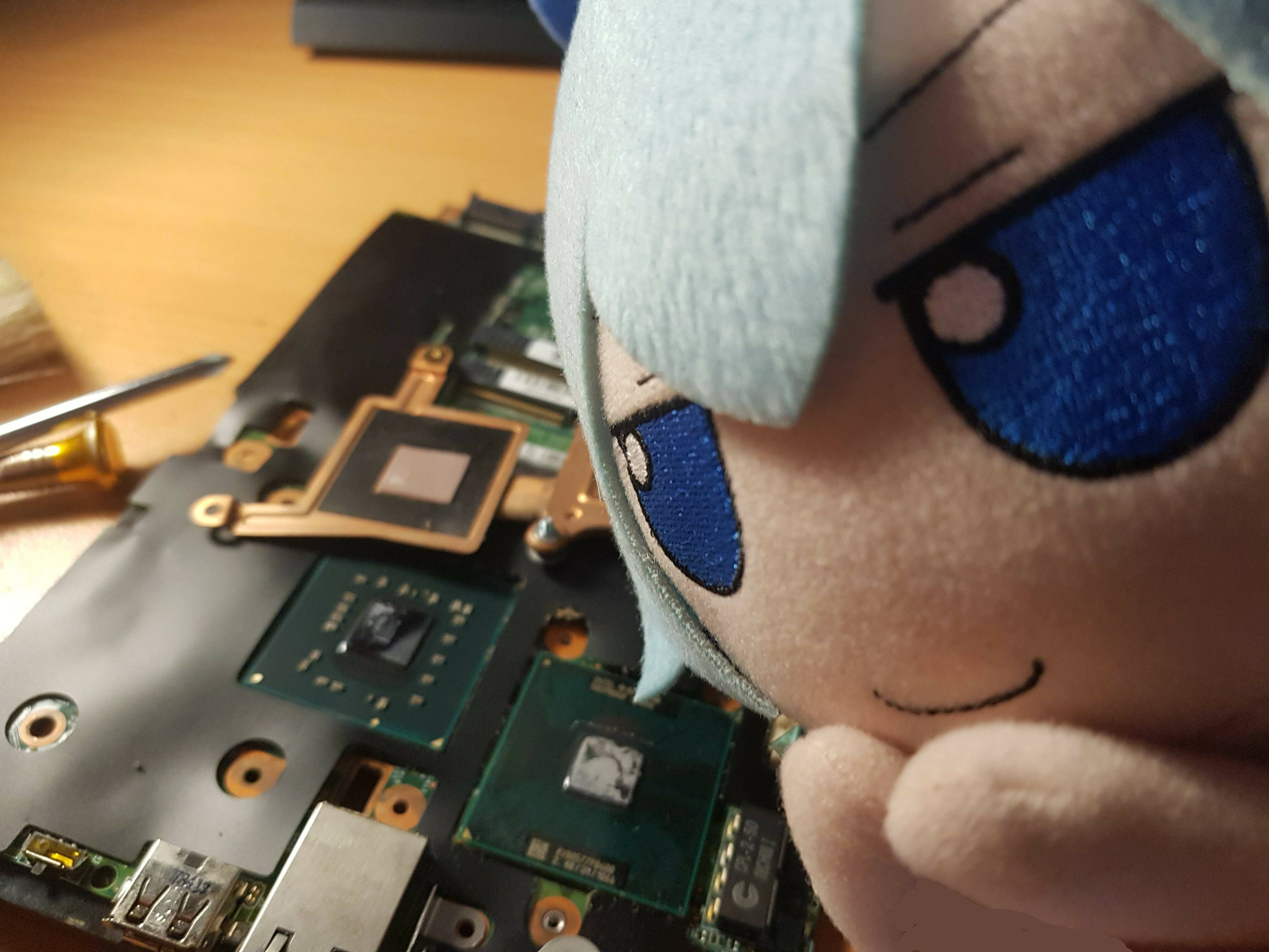
I also replaced the thermal paste on my main x200, the temperatures use to go into the 80's, now stay below 60 all the time, usually 40's.
Cirno helped of course:


Brainfuck interpreter
19/11/2020
I wrote a simple brainfuck interpreter in C.
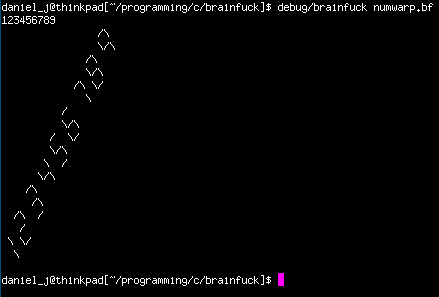
The source code can be found in my git repository.


CHIP-8 interpreter #2 - interpreter
30/8/2020
(See my other CHIP-8 post focussing on graphics here)
ROMs (programs) are compiled to (or written in) bytecode. Bytecode is a kind of instruction set that is designed for execution by an interpreter. CHIP-8 has 2 byte (octet) instructions and is stored most significant byte first. The first byte of an instruction should be located at an even address, and in the case a program might contain sprite data, that sprite should be padded so the next instruction will be at an even location. CHIP-8 has 36 instructions, however the first is ignored by modern interpreters.
Each opcode (with exception of a few such as draw/return) has various operands that can be one of the following:
- lowest 12 bits
- lowest 4 bits
- lower 4 bits of the high byte
- upper 4 bits of the low byte
- lowest 8 bits
/*
 * the opcode is a 2 byte value, while our memory is 1 byte
 * so to get our opcode we need to combine 2 bytes located at PC and PC+1
 * we left shift the first byte by 8 (1 byte) to place it in the high byte
 * and we store the second byte in the lower byte
 */
opcode = (memory[PC] << 8) | memory[PC+1];

uint16_t nnn = opcode & 0x0FFF; 	// lowest 12 bits
uint8_t n = opcode & 0x000F; 		// lowest 4 bits
uint8_t x = (opcode >> 8) & 0x000F;	// lower 4 bits of the high byte, we discard the low byte by right shifting it out
uint8_t y = (opcode >> 4) & 0x000F;	// upper 4 bits of the low byte, so we need to discard the lower 4 bits
uint8_t kk = opcode & 0x00FF;		// lowest 8 bits
With these values known I can continue into the execute stage of the cycle and interpret the correct instruction.
In my interpreter executing an instruction is done within a large, nesting switch statement. Considering the CHIP-8 has 35 used simple instructions, this is a manageable way to do this, however if I were writing an emulator for a real system I would create a function pointer table of handlers which would improve readability vastly.
An example of a few instructions: (note: the memory array is the 4KB of memory the CHIP-8 can access and PC is the program counter pointing to the current instruction)
switch (opcode & 0xF000)
{
	/*
	 * decode highest 4 bits
	 * the highest 4 bits contains the instruction
	 */
	case 0x0000:
		{
			switch (kk)
			{
				case 0x00E0: /* cls (clear screen) */
					memset(video, 0, (WIDTH*HEIGHT) * sizeof(uint32_t));
					draw_flag = 1;
					break;
				case 0x00EE: /* ret (return from subroutine) */
					stack[SP] = 0x0;
					PC = stack[--SP];
					break;
				default: unknown_opcode(opcode);
			}
			break;
		}
	case 0x1000: /*JP addr (jump to memory address nnn) */
		PC = nnn;
		break;
	case 0x2000: /* CALL addr (call subroutine at addr, increment SP and put current PC on top of stack, set PC to nnn) */
		stack[SP++] = PC;
		PC = nnn;
		break;
		...
	case 0x05: /* SUB Vx, Vy (subtract Vx from Vy, store in Vx, if Vx > Vy set V[F] 1, otherwise 0 */
			V[0xF] = (V[x] > V[y]) ? 1 : 0;
			V[x] -= V[y];
			break;
	case 0x06: /* SHR Vx (if the least significant bit of Vx is 1, V[F] set to 1, otherwise 0, then Vx is divided by 2 */
			V[0xF] = V[x] & 0x01;
			V[x] >>= 1;
			break;
	case 0x07: /* SUBN Vx, Vy (if Vy > Vx then set V[F] 1 otherwise 0, then Vx is subtracted from Vy, result stored in Vx */
			V[0xF] = (V[y] > V[x]) ? 1 : 0;
			V[x] = V[y] - V[x];
			break;
	case 0x0E: /* SHL Vx (if the most significant bit of Vx is 1, V[F] set to 1, otherwise 0, then Vx is multiplied by 2 */
			V[0xF] = (V[x] >> 7) & 0x01;
			V[x] <<= 1;
			break;
			...
}
The instruction is stored within the upper nibble (upper 4 bits) of the opcode's most significant byte. This is enough to decode most instructions, however sometimes multiple instructions use the same upper nibble. In these cases the lowest nibble (variable n) and the lowest byte (variable kk) is used to identify which specific instruction is to be executed. Many instructions use the operands (nnn, n, x, y, kk) as extra information for the instructions, such as memory addresses, register numbers, constants, x/y screen positions etc.
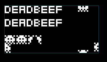
Demonstration of my interpreter playing a breakout game and running a few demos: (the flashing is a byproduct of how the chip-8 is designed - it is intended)
The source code can be found in my git repository.

CHIP-8 interpreter #1 - graphics
17/8/2020
I'm working on an implementation of a CHIP-8 interpreter using SDL2 for graphics and sound, in C. I plan to implement the interpreter in parts and have them accompanied with a website post.
What is CHIP-8
CHIP-8 is an interpreted programming language made in the mid 1970's to allow video games to be easier to create and portable for the incompatible systems of the time.CHIP-8 specs:
- 4KB memory
- 16 general purpose 8-bit registers
- 16-bit I register, used to hold memory addresses
- 8-bit delay timer register
- 8-bit sound timer register
- 64x32 display
- 16-bit PC register, stores the current execution address
- 8-bit SP register, points to the top of the stack
- 16-bit stack consisting of 16 values, allowing upto 16 levels of nested subroutines
- 16 key input, hexadecimal 0-F
- default fontset consisting of 0-F in hexadecimal
- 4KB memory
- 0x0 - 0x1FF reserved for the interpreter, in our case this is where we will put the fontset
- 0x200 - 0XFFF program rom and usable program memory
Graphics
The original CHIP-8 (and the one I'm implementing) uses a 64x32 pixel display. Originally, this would have been viewed on a television of the time, however today we have massive displays - this is just too small. So to fix that we need to implement some scaling, thankfully SDL2 handles this for us.CHIP-8 graphics are drawn using sprites. A sprite is always 8 pixels wide and can be up to 15 pixels tall. Each pixel is a single bit, so each byte has 8 pixels inside it, this equates to a sprite 1 byte wide and up to 15 bytes tall.
As an example, the letter 'E' as a sprite:
| "E" | Binary | Hex |
|
**** * **** * **** |
11110000 10000000 11110000 10000000 11110000 |
0xF0 0x80 0xF0 0x80 0xF0 |
Sprite pixels are not turned off and on as you'd expect, instead they're XOR'd. In my interpreter video memory is an array of 64x32 values. To draw a set pixel of a sprite, the index into video memory is XOR'd with 1 (or in my case 0xFFFFFF). This means if the bit was already turned on, it will be turned off - it's toggling the pixel. In the case of a pixel being turned off because of the XOR, the 0xF register is set to 1 to indicate to the program that a sprite collision has occurred.
If you don't understand the XOR operation see my post detailing how bitwise operations work.
CHIP-8 documentation states that a sprite should wrap around when it is drawn out of bounds. This is achieved with the modulo operator(Modulo is the remained when two numbers are divided, example: 11 modulo 4 = 3, because 11 divides by 4 (twice), with 3 remaining). CHIP-9 has 64x32 display, so imagine the following:
We want to draw a pixel at x coordinate 27. 27 % 32 = 27 - the coordinate stays the same. However, if we try draw a pixel at x coordinate 35 we'll find that 35 % 32 = 3. We've clamped the possible x coordinates to 32, the difference between 35 and 32 is 3, and that is our new X coordinate as it wraps around.
In my interpreter we're treating a 1d array as 2d, so we need to map onto the array (bit is the current bit we're writing, 0-7 for the range of a byte):
destination_in_video_memory = WIDTH*(starty%HEIGHT)+((startx%WIDTH)+bit)
This is the function as it currently stands that draws a sprite to the screen:
void
chip8_draw_sprite(int startx, int starty, uint16_t mem, uint8_t size)
{
	/*
	 * draw sprite located at loc of height size at startx,starty
	 */

	uint8_t byte = 0;
	uint8_t mask = 0x1;
	V[0xF] = 0; /* set collision register to 0 */
	for (uint8_t byteoffset = 0; byteoffset < size; byteoffset++)
	{
		/* loop through each byte from mem to mem+size */
		byte = memory[mem+byteoffset];
		int bit = 0;
		for (mask = 0x80; mask != 0; mask >>= 1)
		{
			if (byte & mask)
			{
				uint32_t pixel = WIDTH*(starty%HEIGHT)+((startx%WIDTH)+bit);
				if (video[pixel] != 0)
				{
					/* if the video bit is already set, we need to set the collision register */
					V[0xF] = 1;
				}
				video[pixel] ^= 0xFFFFFF;
			}
			bit++;
		}
		starty++;
	}
}
This is written only for testing purposes, when I get to implementing the CHIP-8 instructions it will be rewritten.The general gist of the function is:
- set the collision register (0xF) to 0
- loop through size bytes in memory starting at the offset mem
- loop through each bit of each byte
- perform our modulo operations to perform screen wrapping
- if the pixel at our selected video memory location is already set, set the collision register to 1
- XOR the selected pixel in video memory with 1 (in my case 0xFFFFFF) to flip its value
More posts should follow eventually detailing the other components.
The source code can be found in my git repository.

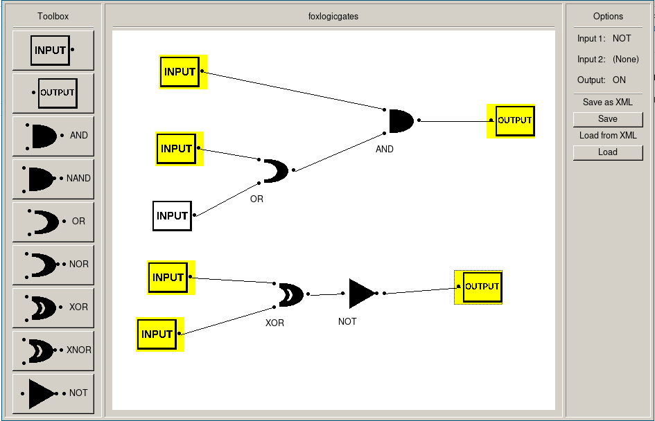
Logic gate simulator
24/6/2020
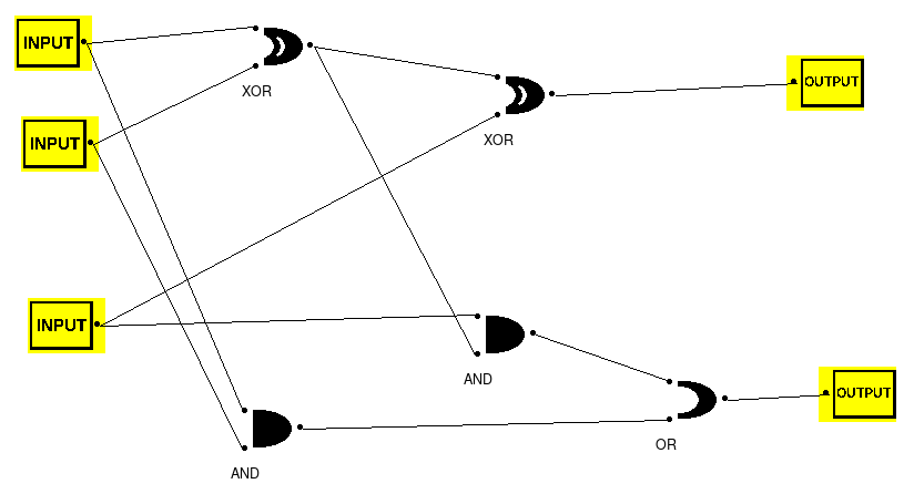
I made a logic gate simulator in C++ using the FOX toolkit.
A working full-adder:
Video of program in action:
Click on an icon and left-click anywhere on the canvas to place that gate (or input/output).
Select a gate by left-clicking on it and press delete to delete that gate and its links.
Hold shift and left-click and drag a link to another gate to connect them.
Click on a gates input to highlight that particular link, press the delete key to delete that link.
Right-click on an input to toggle it on and off.
You can save to an XML file by clicking the save button and selecting a name.
You can also load from an xML file by clicking load.
Some example circuits are provided in the examples/ directory.
To build:
You need the FOX toolkit and pugixml installed. On arch install 'fox' and 'pugixml' packages,
cmake CmakeLists.txt
make
The binary will be in bin/
The source code can be found in my git repository.